Some here are young and have strong backs. 😉you need to think about lifting it,
jeff

after that one you will understand the merit of monoblocks... I'm doing a lot of sports including sailing and crossfit, but I still respect manipulating a 15+ Kg amplifier ! If not for the amp, then for my back 🙂
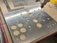
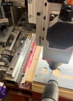
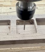
All done the top plate milling. Had to hit it with some 60 grit to take an unfortunate milling mark out of the top. I bolted one of the brass power tube mounts on to see how it looked.
Still needs some filing and sanding on some edges, but this is the final shape.
I also dropped one of my giant aluminum motor run caps and dented it, so I need to decide if I can live with it or buy a new one.

And here’s the dimensions if anyone is curious:

Still needs some filing and sanding on some edges, but this is the final shape.
I also dropped one of my giant aluminum motor run caps and dented it, so I need to decide if I can live with it or buy a new one.
And here’s the dimensions if anyone is curious:
Last edited:
Nice work. I suggest to lightly chamfer the cable holes under the trannies. If not for the cables, then for your fingers 😉
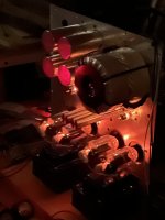
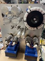
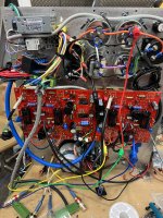
Just some update photos from this past week of getting it assembled. Also changed out the polyethylene coupling caps for some polypropylene.
I’ll tear it down and get the plate anodized once it’s all to my liking and I know I don’t have to drill any more holes.

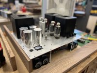
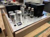
Here’s with the transformer covers in place

And the guts

I’ll tear it down and get the plate anodized once it’s all to my liking and I know I don’t have to drill any more holes.
Here’s with the transformer covers in place
And the guts
Brought it up under power for the first time in the chassis today. Wish I could say it went smoothly, but there were two casualties. I somehow didn’t realize I had a 1 volt meter in place of the 800v b+ meter, so that let out the smoke almost immediately while turning the variac dial. The second thing happened around 500v where the insulation between the mosfet for the screen regulator broke down and shorted to the heat sink. Luckily I have spares. Brought it up to 600v and let it idle for a few minutes before calling it a night.
Attachments
Are there any other threads or articles that discuss the higher power versions of this stereo board? Changes, schematics, power supplies. Thank you
They are most likely buried in Pete's original thread here: https://www.diyaudio.com/community/threads/posted-new-p-p-power-amp-design.151206/Are there any other threads or articles that discuss the higher power versions of this stereo board? Changes, schematics, power supplies.
George aka @Tubelab_com might be able to pinpoint some specific examples. He has built a few high powered amps.
jeff
My amps in the current rotation are Millet's Engineers Amp AND, adjusting for its much higher gain, a pair of evaluation mods of the LME49830 driving mosfets. They both sound great, but obviously a bit different.
I have built both the "Engineers Amp" and the "DCPP". I splurged and got the pre-fab chassis for the monoblocks, and felt they were worth the $
Another small update. Milled up some walnut for the sides of the amplifier, and started machining the front plate. Found I had fried the screen regulator zeners when I had the short on the mosfet, and I also broke the knob off for the feedback potentiometer, so parts are on order for that.
Attachments
I built a version last winter that used an oversized PT and OT to get a little more power out of the stock tubes. I posted about it earlier in this thread.Are there any other threads or articles that discuss the higher power versions of this stereo board? Changes, schematics, power supplies. Thank you
- Home
- Amplifiers
- Tubes / Valves
- Build Log of 100+ watt Pete Millet “Engineer’s Amplifier”