Those look like the “24 to 28 watt” plates. The black plate Sylvania looks just like the two good 6CB5A’s I got from Stan. If you look at post 11 the five in the middle all have the same size plate, and the pair with the bigger caps are 21LG6. The others are using the same (supposedly 28 watt) plates, but run with 9W heaters instead of 12. My guess is exceeding their 17.5 watt ratings and running them up at the full 28 wouldn’t cause a bit of grief. Those types were 3 and 4 bucks. There seems to be a lot of stuff available to coax the full 100 watts out of this design - without spending upwards of $65 a pop. A pair or two isn’t awful, consudering what new 6550’s go for these days. But with dwindling stocks of these sweep tubes you may not get the same ones again in 10 years. You have to consider spares and a full set for a retube. So that 4 your want/need becomes 10 or 12. And if your design needs 12 - well, you get the picture.
There are two things that determine how much power you can squeeze out of a given tube. Obviously, the plate dissipation rating determines how much heat the plate can shed before it gets too hot. The plate must be able to dissipate the power that is applied from the power supply minus the amount of that power that gets turned into audio. The efficiency of the tube itself affords the greatest influence on the losses, and the heater power has one of the largest effects on that efficiency. Over the history of the vacuum tube the coating used on the cathode has evolved affording better emission efficiency at the same heater power, or lower heater power for a given efficiency. Somewhere in the 60's a rather large improvement occurred. By this time many TV sets had moved to series string heaters, so the heater power was not easily changed without a complete redesign with a new tube lineup.
My experiments with some golden oldie 6L6GA's revealed that attempting to pull more emission from a tube than the "space charge cloud" could support results in a tube arc, which is basically a lightning bolt from cathode to plate. This discharge flowed enough current to cause a 1 ohm 2 watt cathode sense resistor to explode, not once, but twice. In both cases the tube survived and appeared to function normally after replacing the resistors and turning down the power level. The "BANG" point was about 110 watts per pair on 1940's vintage tubes into a 3300 ohm load on 500 volts well into AB2. The 6L6 types have a 5.7 watt heater.
In contrast the 6LW6 types have a 16 watt heater in a much larger cathode. A pair of those under the same conditions will make about 140 watts and don't need AB2 to get there.
TV sweep tubes typically have a much larger cathode with more heater power than a typical audio tube having a similar plate dissipation rating. This is why you can squeeze them harder.

There is the 17/22KV6A capless sweep tube around too. Rated 28 Watt for regulator service with reduced screen Watts (2.0 W). For Sweep tube duty, more like 22 Watts with 3.5 W screen. Inexpensive, but they have the annoying Novar base. (Hard to find good sockets, but there are some around) The Sylvania ones tend to have an antique looking "Edison" style glass tip up top, with a more longish bottle. ( 1.5 inch diameter tube like 6HJ5 ) With a socket adapter you can make them look like Octal tubes. Last picture: 6HJ5 in center, 17KV6A on right end.


Last edited:
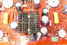
How close should these grid stoppers match? Had to parallel four 1/2W resistors to get 2W. Resistance ranges from 520 to 570 ohms.

I could only get my hands on 1/2W. The original thread mentions several times to use 2 watt resistors here. I completely forgot to try and sort and measure before soldering them in!
Well now I'm wondering why. I realize that 1/2w is the recommended minimum.The original thread mentions several times to use 2 watt resistors here.
jeff

Here’s the reference in the original thread. I don’t think it will matter too much that my values don’t all match, but if there’s a reason they should be closer, please let me know. I measured again, 3 of them measure very close to 530 ohms, and one is 578; nominal should be 550.
R8,9,10,11 on the schematic are screen (G2) stoppers, not grid (G1), hence the higher wattage.
jeff
jeff
Ah, ok makes sense. Thanks. It bothered me enough that I pulled out the 578ohm group and replaced them. All pretty close to matching now. I know four in parallel doesn’t look nice, but at least they won’t be seen.
I now have most of the resistors installed. Haven’t installed any feedback resistors, as I’m not sure about the global feedback yet, and the schade resistors are going to stick up quite a bit; using a couple 110k in series to handle the voltage. I also have yet to install a few resistors to the tube sockets, as I need to look at the pin out and see what makes the most sense for my octal sockets.
Haven’t done any serious soldering since college 16 years ago, so it’s not perfect, but I think it’s pretty good.
Haven’t done any serious soldering since college 16 years ago, so it’s not perfect, but I think it’s pretty good.
Got all the board mounted components installed. The bias pots will be chassis mounted, and I’m thinking about a chassis mounted global feedback knob. I attached two 120k resistors in series for the schade feedback to handle the voltage, and used rubber electrical tape to cover the joints. I hope 240k is fine instead of 220k for this. I also installed 1000pF 15kv caps for the OPT anti ringing. 
Powered up for the first time today. C- and heater supplies disconnected, and no tubes installed. Everything seemed normal. Only turned up the variac enough for 400V B+. I don’t have any heat sinks on the Mosfets in the power supply yet, and it’s temporarily wired for 6HJ5 tubes.
Anything particular I should be testing before plugging in tubes? I checked voltages around the board to see if anything seemed abnormal, but so far so good as far as I can tell.
Anything particular I should be testing before plugging in tubes? I checked voltages around the board to see if anything seemed abnormal, but so far so good as far as I can tell.
Attachments
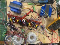
I'd be tempted to put some kind of temp. heatsink on them before letting her rip, even if it's just a piece of aluminum angle.I don’t have any heat sinks on the Mosfets in the power supply yet
jeff
Last edited:
I used the heatsink from a really old CPU, probably an i486 chip, in my old test board. The B+ to the output tube plates did not go through the board and the board itself ran from about 320 volts. Higher voltage to the board might require a bigger heat sink. The hottest things on my board were the 10M45 chips, but I didn't have any heat sinks on them at all.
Attachments
I will run a heat sink before testing with the tubes for sure. The only reason I haven’t is I don’t have any insulated thermal tape for them right now.
When I said 400V B+, I meant plate voltage. Closer to 200V on the board B+. Got nervous when I smelled smoke, but realized my it was my soldering iron cooling off (I shut the fan off to listen for anything strange).
When I said 400V B+, I meant plate voltage. Closer to 200V on the board B+. Got nervous when I smelled smoke, but realized my it was my soldering iron cooling off (I shut the fan off to listen for anything strange).
Here is my tube porn pic. My build is going about the same pace as yours. Powered up a few days ago and biased. Used random used 6JN6 I had. Eventually will run all of them in my utracer to find the best sets. Did not put a scope on the output yet but couldn't resist hooking them up to some speakers. It sounds great driving them with my bench computer soundcard.

Wired up the rest of the supplies, put some heatsinks on the mosfets, and brought it up to 115VAC in. Got 630VDC to the plates. Only getting 141V for the screen. Will this be enough? I’m using IXTP15N50L2 mosfets, as the XQPF8NxxC is NLA.
Brought it up with the tubes in. Dummy loads on the OPTs, inputs shorted, bias set low, and one of the 6HJ5s began to glow red. Shut it down immediately. I’ve double checked my wiring, and can’t find anything. Tempted to bring it up again with a meter across the bias test point.
Any ideas? Can these tubes safely be run horizontally? They are right now, as it’s not practical for me to run them vertically at the moment.
Any ideas? Can these tubes safely be run horizontally? They are right now, as it’s not practical for me to run them vertically at the moment.
Quickly checked with multiple meters hooked up, all of the bias currents climb too high (over 100mA) It’s possible that I don’t have enough C- due to only bringing the amp up to 3/4 power on the variac, but now I’m nervous to test this theory by applying full power.
- Home
- Amplifiers
- Tubes / Valves
- Build Log of 100+ watt Pete Millet “Engineer’s Amplifier”