Page 39 in the integration guide:
http://www.twistedpearaudio.com/doc...-Buffalo_III_DAC_Integration_Guide_V1.2.3.pdf
thanks alot
how many idependent psu that you need for buffalo dac if you want to feed as many independent psu to each section of the dac?
i am new to this dac. so my quick look at the guide, i think can use 5 separate psu:
- 3 separate psu for 3 trident
- and 2 separate psu for analog section.
anything else?
is there any information on the current draw of each section? as i would like to supply with CLC raw psu only to each section. any possible problem by using unregulated raw power supply?
thanks
erwin
Last edited:
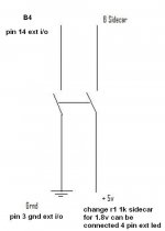
Good catch Leif. Thanks Russ! I attached a corrected image noting B4 in this post. I don't have the power to delete or change the image in my prior post but would encourage those who do to change it or delete it. Thanks!
Do I ground B4 to the chassis, VG on the Sidecar or a ground on the external I/O connector header?
I suppose pin 3 GND of the external I/O connector, Russ or Brian could you confirm?
I suppose pin 3 GND of the external I/O connector, Russ or Brian could you confirm?
Yes GND at EXT-IO which is the same as VD GND or any of the power GNDs.
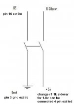
It's necessary to change R1 10K in Sidecar for R1 1 K in Sidecar?
It depends, if your driving it from ~5V the 10K will work fine. If your driving it from an LED spot (1.8V) you will definitely need something around 1K (even a bit less is ok)
Would it not also make sense to turn off input remapping (B7) when sidecar is switched to i2s?
Would it not also make sense to turn off input remapping (B7) when sidecar is switched to i2s?
No - for sidecar you would just leave it on. 🙂
You could switch it off for SPDIF, but it is not necessary.
If I got it right it should all be connected as shown in the image, Right?The auto-detect feature is especially prone to false positive on I2S data. This means when using sidecar that if you have the DAC SPDIF multiplexor set to receive either channel 2 or 4 (which map to D2 and D4 on DIN) it will *very* likely unlock the DPLL from time to time as it mistakes the PCM data for a new SPDIF signal and attempts to lock onto it in vain, only to once again soon re-lock on the I2S/DSD. This is especially true at high sample rates (192Khz and above).
The Buffalo III firmware exposes the SPDIF auto-detect register to the user using I/O B4. When B4 is high (default state - switch 2:5 open) SPDIF auto-detect is enabled. When low (same switch "on"/closed) then auto detect is disabled (or "bypassed" if you will).
If you wish to use the 2-bit selector to switch between 4 SPDIF sources (using the SPDIF4 module) and the sidecar to switch between I2S/DSD and SPDIF you should always pull I/O pin B4 low on the Buffalo 3 when you have I2S/DSD selected. The best way to do this is with dual pole single throw switch. One pole should be connected to GND and "B4" on the Buf III I/O header - the other to 5V and "B" on the Sidecar. In this way when PCM/DSD is selected SPDIF auto-detection is disabled. You also get to use all 4 SPDIF selections.
Cheers!
Russ
But where to get the 5V from?
Attachments
One of your PSUs will do.
You can actually get it from the VD terminal on the Sidecar, which is connected via the ribbon cable to the Buffalo's VD terminal.
You can actually get it from the VD terminal on the Sidecar, which is connected via the ribbon cable to the Buffalo's VD terminal.
Right! Thanks!
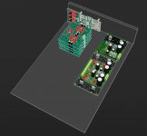
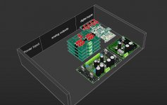
This is currently where I am with my BIII project: http://imgur.com/TxNPb The question I have is - is there an issue with the distance of the S/PDIF Switcher Board to the BIII? If needed, I could switch places with the IVY boards and S/PDIF Switcher board. I don't know if those I2S lines can be that long... will I have unlock issues?
The acrylic back panel is only temporary and is used as a placeholder for the final panel, which will be metal.
Any other electrical design-related questions are appreciated!
http://imgur.com/TxNPb
The acrylic back panel is only temporary and is used as a placeholder for the final panel, which will be metal.
Any other electrical design-related questions are appreciated!
http://imgur.com/TxNPb
Last edited:
Cool build. Perhaps you could shorten down the wires a bit by placing them like this.
Great explanatory graphic! (What did you use to make it?) I can't really mount the BIII on the side, since it piggybacks on top of a USB-I2S converter, and then my custom 2-8 channel switcher is mounted on top of the BIII.
*If* the long lines are an anticipated problem, I could always swith places with the S/PDIF board and the IVY boards, and move the inputs to the same side as well. But then, the lines from the 2-8 switcher to the IVY boards will be longer, too.
Ok. In that case I would place the dac board, the sp-dif input rca/optical etc. and those other boards in that stack to the same side of the ivy`s and align the sigma11 and sigma22 to keep the wires as short and to the point as possible (I use Google Sketchup 8 to make the 3d models).
Attachments
Ok. In that case I would place the dac board, the sp-dif input rca/optical etc. and those other boards in that stack to the same side of the ivy`s and align the sigma11 and sigma22 to keep the wires as short and to the point as possible (I use Google Sketchup 8 to make the 3d models).
Did you use the regular or the PRO version of Sketchup?
- Status
- Not open for further replies.
- Home
- More Vendors...
- Twisted Pear
- Buffalo III - flexibility without compromise.