
Almost dual opamp will work like 5532 etc. just check the pin out diagram to make sure +ve and -ve rails are same and output pins are the same. OPA1642 is another one.
Thanks! That's what I thought, I have a few boards built 'by the book', and now 2 with OPA1612 and all Dale CMF or Vishay MBB resistors, I think it sounds the same lol. One day I will figure out how to maybe do some measurements between the boards.
Most opamps will measure very similarly but the 1656 in my experience has that nice dominant second harmonic even though it is very low distortion. 1642 is also similar.
Hi 🙂
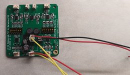
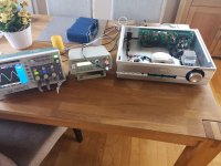
Just tested my BTSB Buffer in my preamp with sign.gen. and scope. Gain set to 6dB. Working just fine
Regards
J.R
Just tested my BTSB Buffer in my preamp with sign.gen. and scope. Gain set to 6dB. Working just fine
Regards
J.R
Attachments
-
 Skjermbilde 2022-05-27 022445.jpg159 KB · Views: 214
 -
 Skjermbilde 2022-05-27 022309.jpg259.5 KB · Views: 204
 -
 IMG_20220530_164604.jpg380.3 KB · Views: 212
 -
 IMG_20220530_184946.jpg363.5 KB · Views: 194
 -
 IMG_20220530_185510.jpg391.2 KB · Views: 203
 -
 IMG_20220530_201714.jpg412 KB · Views: 215
 -
 IMG_20220530_185520.jpg394.3 KB · Views: 215
I am not sure if this has been discussed before, but would it be possible to get a fully built board?
Yes, but only for the panel mounted ones. I am planning on having a small batch made in a month or so. I asked if people were interested in the other thread.
https://www.diyaudio.com/community/threads/btsb-panel-mount-buffer.379030/#post-6979699
https://www.diyaudio.com/community/threads/btsb-panel-mount-buffer.379030/#post-6979699
Hi 🙂Hi 🙂
Just tested my BTSB Buffer in my preamp with sign.gen. and scope. Gain set to 6dB. Working just fine
Regards
J.R
Just got my pre-amp measured by a pro. friend of mine. Translation by Google from Norwegian > English .
Thank you for your pleasant visit yesterday.
We were able to make a number of measurements when we got our act together and had focus. But when two gentlemen interested in electronics meet, it quickly turns into a bit of extraneous talk too 😁
Gain:
Due to the hopeless Chinese firmware that controls the volume control and the display, there is a deviation in the presented gain on the display. When the volume is at maximum (0dB), the actual gain is +5.43dB. Otherwise, the scale goes down.
THD+N curve
In this measurement, one looks at the proportion of distortion and noise in relation to the signal. This test tells a lot with one picture, but at the same time you don't see what type of noise there is, and you also don't see what type of distortion there is.
We see that the right and left channels match well.
We see the classic curve where the noise floor dominates the measurements up to 1V before distortion takes over. It is natural that when the signal is as small as 60mV, the noise will be dominant, and shows that it is at 0.009%. Since the noise is constant, the difference between noise and signal will become larger as the signal increases. With a 1V signal, we see that the proportion of noise is 0.0005%. It is very good.
Above 1V, however, something happens. There, there is some form of distortion that starts to increase as the signal increases. To see exactly what is happening, we have to look at other measurements. Let's look more precisely at what happens at e.g. 2V on the curve above where we see that THD+N is approx. 0.0015%.
Here is a measurement of the spectrum at exactly 2V:
We see that it is the third harmonic that dominates the distortion. It is almost 100dB below the signal, so it is probably not audible. We also see from this measurement that the noise floor is approx. 140dB below the 2V signal and it is completely free of mains noise. Good shielding and regulation that is.
I am probably pretty sure that it is the MUSES chip that adds this third harmonic since it is not particularly fond of loading its output.
The first thing I would look at to investigate the problem are these resistors here:
Noise.
Lest channel Right channel
The noise is at 5-6uV. It is a good low level and you must have a power amplifier with high gain and sensitive speakers because this will sound like hiss.
We also see that there is some radiated noise at 150Hz and 250Hz - presumably from the transformer - on the right channel. But -130dBV is so small that it can never be close to audible.
Frequency response.
Here we want as flat a curve as possible. From 20 to 10kHz, the deviation should be within a maximum of 0.1dB so that the sound is not affected. A slight damping at 20kHz is normal and is very difficult to hear.
Volume at 0dB (Right and Left)
Exemplary with 20kHz down only 0.2dB
Volume of -15dB
With the volume adjusted down 15dB, we see that the roll-off at 20kHz has increased slightly and is 0.45dB. This does not change with other volume settings either.
The fact that it changes by 0.25dB when MUSES has muted the volume probably has something to do with how it is implemented. Possibly due to the capacitors on the next buffer stage. Still good for approved 👍
THD+N vs frequency.
Here we look at how the distortion changes as a function of frequency from 20Hz to 20kHz. We want the distortion not to increase as the frequency increases.
This test is run with a bandwidth of 80kHz. This means that the measuring instrument captures distortion up to 80kHz. It's really unnecessarily loud as no one will be able to hear a third harmonic distortion of a 10kHz note since it will occur at 30kHz, but we include it anyway to see how the preamp handles this. The test was run with 1V at the output.
CMRR (Common Mode Rejection Ratio)
Here we look at how good the amplifier is at removing ground noise from the signal. Of course, you don't want earth voltages to interfere with the signal. This is a property you only get with balanced cabling. Usual values are 50-60dB attenuation. It usually works in a normal home system that is not bothered by a lot of ground noise, but the higher the better.
An additional thing measured in this test is how the input stage handles different source impedances on the front stage. I therefore use a test box where I deliberately create an imbalance of 10 Ohm between the two balanced conductors (HOT and COLD). Usually the CMRR drops dramatically if the source impedance is not equal.
This is how the result with the volume adjustment set to -10dB. NOTE: All values need to be adjusted 6dB as I now realize I forgot to correct for this in the calibration. -80dB on the curve therefore corresponds to -74dB.
We see that with the same source impedance (left) we get the best result of -74dB at 1kHz.
With different source impedances, this exercise is much more difficult, but the attenuation at 1kHz is still -64dB.
These are absolutely approved results.
IMD (InterModulation Distortion)
Then there is the acid test. Nothing is more difficult than handling two high frequencies at the same time without weird things happening.
Here I send in two signals at the same time. One at 19kHz (1V) and one at 20kHz (1V). The result of this is that you get a modulation of the signal where you get cancellation and amplification of the two signals 1000 times a second. The only thing you want to see are the two signals, but signals often appear at 1kHz and also at 16kHz, 17kHz, 18kHz and 21kHz, 22kHz, 23kHz, etc.
Here are the results for two voltages at the output. Note the curve shape of the signal at the bottom where you can see that the signals respectively cancel and amplify with 1ms intervals.
Summary.
This is a preamp that, matched with an amplifier with enough gain, will be completely transparent and noise-free. The build quality is solid and it looks very good.
The only point of appeal is the increasing distortion above 2V. But it is important to be aware that it is rare to have more than 2V at the output. An amplifier usually has around 27dB gain (22.4 times), and with 2V realized it will have 44.8V out on the speakers. That corresponds to 484W on a 4 ohm speaker, so something is needed before you end up in that area.
J.R
Last edited:
Thank you for the extensive test Ine. -140dB noise floor is better than what I was able to measure as my equipment doesn’t go that low. Good to know. Surprising that the technician said that there was not enough gain. Did he know that there is a DIP switch to select 0/6/14/20 dB gain? It’s a very transparent preamp/buffer from what I can see. Also, the BTSB doesn’t have a Muses chip. What is he referring to? The digital volume controller?
Hi @xrk971 🙂Thank you for the extensive test Ine. -140dB noise floor is better than what I was able to measure as my equipment doesn’t go that low. Good to know. Surprising that the technician said that there was not enough gain. Did he know that there is a DIP switch to select 0/6/14/20 dB gain? It’s a very transparent preamp/buffer from what I can see. Also, the BTSB doesn’t have a Muses chip. What is he referring to? The digital volume controller?
There is a movie called "Lost in translation" 😆
And that just happend here, I blame Google 🙄
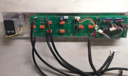
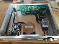
Here is a picture of my pre-amp:
It's built like this: Input selector (relays)> Muses 72320 Volume chips > BTSB> Output selector (relays).
Some misunderstanding there (blame Google). The BTSB was set up to give 6dB gain, we measured 5.43 dB. Not a big deal, really. But whats concerning is this:Surprising that the technician said that there was not enough gain.
We see that it is the third harmonic that dominates the distortion. It is almost 100dB below the signal, so it is probably not audible. We also see from this measurement that the noise floor is approx. 140dB below the 2V signal and it is completely free of mains noise. Good shielding and regulation that is.
I am probably pretty sure that it is the MUSES chip that adds this third harmonic since it is not particularly fond of loading its output.
The first thing I would look at to investigate the problem are these resistors here:
The third harmonic is pretty high, and I'm pretty sure that it is the Muses volume chips that adds this third harmonic. The Muses don't like a heavy load on their output. A easier load would probably get the third harmonic down. My tech guy said:
The first thing I would look at to investigate the problem are these resistors in the input bootstrap.
He mentioned something about raising the values of the resistors to something much higher.
So, my question is: Can this be done ? Would the bootstrap still work properly ? Maybe this is a question for JH, I don't know ?
Regards
J.R
Last edited:
Yes, it is the Muses chip that adds that distortion because my measurements don’t show this. I think the nominal load is 50k ohm. Should be easy for most sources to drive. I’ll let Jhofland answer but I think you could probably double the 49k9 R6 resistor to 100k without a problem.
This was 2Vrms output from the BTSB.

This was 2Vrms output from the BTSB.
Hi Ine,
What about putting the Muses volume controller after the BTSB? It really is meant as the input buffer as it provides Bal and SE input. You would probably use the SE output of the BTSB to drive the Muses followed by a simple opamp buffer stage to make sure you have enough drive current.
What about putting the Muses volume controller after the BTSB? It really is meant as the input buffer as it provides Bal and SE input. You would probably use the SE output of the BTSB to drive the Muses followed by a simple opamp buffer stage to make sure you have enough drive current.
That's my intention with my project. 🙂 Looking forward to implementing them when life calms down a little!Hi Ine,
What about putting the Muses volume controller after the BTSB? It really is meant as the input buffer as it provides Bal and SE input. You would probably use the SE output of the BTSB to drive the Muses followed by a simple opamp buffer stage to make sure you have enough drive current.
Hi 🙂Hi Ine,
What about putting the Muses volume controller after the BTSB? It really is meant as the input buffer as it provides Bal and SE input. You would probably use the SE output of the BTSB to drive the Muses followed by a simple opamp buffer stage to make sure you have enough drive current.
NOT an option to do by me. Muses Volume after the BTSB will only increase the THD in the Muses. Sorry . I sent a PM to JH, but no response.
Watching this with interest. I was planning to use the muses before the BTSB buffer, so I would only need a 2 channel volume control for SE signal and I can use both the XLR and SE outputs from the BTSB with volume control.
Don't hold your breath, as no one is willing to calculate new resistance values for the input stage of the BTSB. (So it would be a easier load for the Muses Volume).. I will use another gainstage in my pre.Watching this with interest. I was planning to use the muses before the BTSB buffer, so I would only need a 2 channel volume control for SE signal and I can use both the XLR and SE outputs from the BTSB with volume control.
J.R
Last edited:
Yes, I don’t think you are going to have an analysis of what resistance to use. Easiest to try changing the resistor to a higher value and see if it works.
- Home
- Group Buys
- BTSB Buffer - SE/Bal to SE/Bal Buffer GB