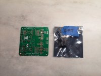
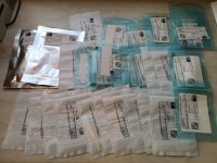
The panel mount version uses OPA1637, so can drive 50mA - maybe 600ohm headphones and not too loud. The other version uses LME49724 which can drive 80mA I think so that may have worked a bit better.
You can easily give it a circuit for muscle to drive balanced headphones. A pair of PCA daughter boards can be connected to the outputs of the BTSB to drive a balanced channel. You would need 4. Building it is easy though. I have done this before and it’s pretty great sounding.
https://www.etsy.com/listing/715372...ck_sum=7d234796&ref=shop_home_active_28&sca=1
A pair of Yarra/M2X breakout boards can be used to hold the boards.
https://www.etsy.com/listing/103315...079&click_sum=001c87d2&ref=shop_home_active_8
https://www.diyaudio.com/community/threads/xrk971-pocket-class-a-headamp-gb.302859/post-5121677
Last edited:
Hi,
I will soon receive my BTSB SMT v1.2 pcb. Been reading through this thread, and I'm wondering: Do this pcb need any modifications ?
J.R
I will soon receive my BTSB SMT v1.2 pcb. Been reading through this thread, and I'm wondering: Do this pcb need any modifications ?
ThanksHi Folks,
I am sorry to tell you this, but there is an error on the BTSB board v1.1 and v1.2 and the SMT boards. When I built the verification board, I failed to test the SE outputs - I have been told by a member who contacted Jhofland and together, they determined that the phase on on the J36 connection is flipped. Having just ordered a new set of boards (now with this error), I will have to get a new set ordered and send out replacements to everyone who has already bought one. If you have not started populating them, you can wait for the new ones. Or if you have no need for SE out, you can go on as usual. There is a workaround by crossing some resistor legs on the TH board. The SMT board is not so easy as it requires cutting a trace and adding a jumper.
J.R
Where do we get the TH 1.3 boards?The SMT v1.2 does not need any mods. It’s the latest version of the SMT board. V1.3 is the latest TH board. V1.2p is the latest version of the panel mount board.
Thanks
From my shop, select the TH (bare) PCB option.
https://www.etsy.com/listing/833727...10&click_sum=b2fcc228&ref=shop_home_active_15
https://www.etsy.com/listing/833727...10&click_sum=b2fcc228&ref=shop_home_active_15
I seem to recall there being a turn on thump last time I used the BTSB. Is this so? And if so is it due to the servo?
There is no servo and I would leave it powered on 24/7 connected to a walwart. It draws very little power (under 2W) and no provision for anti-thump has been built in.
I think U4 creates a That-inspired common-mode bootstrap. (someone told me....)
J.R
Thanks for pointing me in THAT direction 😉 . Figure 3 in this article shows remarkable similarities and does in fact describe the function of U4 as a DC servo.
https://audioxpress.com/article/getting-the-most-from-that-s-balanced-line-drivers-and-receivers
We are not using THAT chips - all OPA1656 implementation except for the output balanced driver - but yes, U4 is the bootstrap opamp. I’ll let Jhofland, the circuit designer expand on that if you have any other questions.
Why not ? Better tolerance on the resistors is one good reason. 1% against 0.5% or less for some of them.
Another thing: Where do you find the op-amps in a DIL8 package ? They are all in a soic8 package. So, better to do the whole thing with SMD's 🙂
Another thing: Where do you find the op-amps in a DIL8 package ? They are all in a soic8 package. So, better to do the whole thing with SMD's 🙂
- Home
- Group Buys
- BTSB Buffer - SE/Bal to SE/Bal Buffer GB

