Great looking work Chris. SMDs can be real fun! I always order the resistors and caps in multiples of 10. When go flying out of the tweezers, they’re usually gone for good at my bench. Almost impossible to find in carpet too. 🙂
Beautiful work, Chris! 👍
Great thing that you stocked up on parts long ago. It’s getting harder and harder to build projects lately. Do they all work well?
Thanks for taking on four at a time.
Great thing that you stocked up on parts long ago. It’s getting harder and harder to build projects lately. Do they all work well?
Thanks for taking on four at a time.
I’ll let Jhofland, the designer of the BTSB answer this. The balanced input circuit uses three halves of an OPA1656 or OPA1642. The balanced driver uses either LME49720 or OPA1637. When I built and measured this circuit, the noise floor is below what my system can measure (better than -130dB relative to 2Vrms full scale - or 0.63uV rms). There’s no noise to be heard if you look at the FFT below. The small blip at 60Hz is actually EMI pickup from the air onto the signal cable even when the BTSB was turned off.Thanks for all the answers, XRK.
Cool.
Ok, I'll figure this out if I go for this option.
My doubt comes from the output stage of the circuit:
View attachment 1007167
In the schematic, it seems that the inputs of the U7B opamp are coming from the balanced line driver outputs just before R41 and R42. So if I omit the balanced line driver chip, will the U7B work? Or will the signal reach U7B via R33 and R35?
I'm no expert. 🙁 I was just referring to what I've read in Doug Self's books. If you see his Audio Power Amplifier Design Handbook (5/ed, 6/ed, take your pick), you'll find a chapter which talks about input circuits, and there he discussed balanced input circuits. He first shows a balanced circuit with just one opamp and passives, and then says that this is far worse than a single-ended input with one opamp. In his words, "the noise output of a 4 x 10 k balanced input amp using an NE5532 is -105.1 dBu, which completely swamps the power amplifier EIN and degrades the overall noise performance by 17.5 dB."
The book illustrates the impact of the input stage noise on the overall power amp noise through this table:
View attachment 1007168
He then goes to design multi-opamp balanced inputs which really cut down the noise of the input stage. He explores other low-noise opamps too, beyond the NE5532. He also has such an input stage on his website: http://www.signaltransfer.freeuk.com/lownoisebal.htm
I was wondering how we are getting low noise in our balanced input circuit without all these techniques.
Hope I'm making sense?
Last edited:
Thanks! I haven’t had an opportunity to test them yet. I just finished soldering them and was eager to get the completion photos out. I have to track down a 12V power supply and build up some adapter cables to give them a test drive.Beautiful work, Chris! 👍
Great thing that you stocked up on parts long ago. It’s getting harder and harder to build projects lately. Do they all work well?
Thanks for taking on four at a time.
Hi Folks,
I have had an a GB interest list for ready to run panel mount BTSB boards on my Manufacturers forum for some time now. But seems no interest. Just today though someone PM’d me saying that he has interest.
Perhaps I should ask it again? $165 ea and we need interest in 15 units to make it viable.
They will look as good as Chris’ boards! LOL


Beautiful product photography, Chris!
I have had an a GB interest list for ready to run panel mount BTSB boards on my Manufacturers forum for some time now. But seems no interest. Just today though someone PM’d me saying that he has interest.
Perhaps I should ask it again? $165 ea and we need interest in 15 units to make it viable.
They will look as good as Chris’ boards! LOL
Beautiful product photography, Chris!
Ha! Just me and my iPhone 😛Hi Folks,
I have had an a GB interest list for ready to run panel mount BTSB boards on my Manufacturers forum for some time now. But seems no interest. Just today though someone PM’d me saying that he has interest.
Perhaps I should ask it again? $165 ea and we need interest in 15 units to make it viable.
They will look as good as Chris’ boards! LOL
View attachment 1011480
View attachment 1011481
Beautiful product photography, Chris!
Just posted my build discussion here:
https://www.diyaudio.com/community/...to-se-bal-buffer-build-from-wisconsin.381440/
https://www.diyaudio.com/community/...to-se-bal-buffer-build-from-wisconsin.381440/
Hi XRK,
I thought you're using a DC-to-DC converter followed by some inductors as LPF to get clean power to the audio circuits. I am not seeing the inductors in the schematic. Am I confusing this circuit with something else you built?
I thought you're using a DC-to-DC converter followed by some inductors as LPF to get clean power to the audio circuits. I am not seeing the inductors in the schematic. Am I confusing this circuit with something else you built?
Sorry, I found the inductors, please do not bother to respond. My apologies.Hi XRK,
I thought you're using a DC-to-DC converter followed by some inductors as LPF to get clean power to the audio circuits. I am not seeing the inductors in the schematic. Am I confusing this circuit with something else you built?
I just got more BTSB SMT v1.2 PCBs in. I will put these up in the shop again soon. Thanks for your patience.
Here:
https://www.etsy.com/listing/833727...ck_sum=3536b4cb&ref=shop_home_active_16&crt=1
Choose SMT Bare PCB for the v1.2 (latest) of TH bare v1.3 (latest)
Note that there is also a Panel Mount version 1.21p that allows XLR and RCA jacks to be mounted to the back panel.
https://www.etsy.com/listing/938031...32&click_sum=9e8d85b8&ref=shop_home_active_11
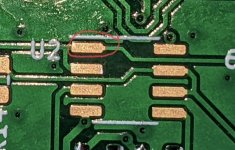
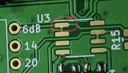
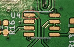
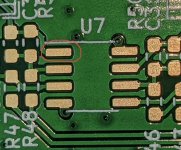
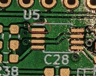
Hi X & Chris: I'm building my panel mount board now and in scrutinizing Chris' nice pics. I want to check if I have pin 1 of each opamp correct on the board. See red circle in pics for my guess as to pin #1.
Thanks, Pete
Thanks, Pete
Attachments
-
 3BA16B64-FB5C-4862-900B-1AF2EED21DA4.jpeg92.1 KB · Views: 99
 -
 A28FE78D-E3BB-42B2-B06E-BD4AC3600708.jpeg63.5 KB · Views: 116
 -
 37DB87A4-4C8F-4D4C-9181-D903E975553C.jpeg90.5 KB · Views: 103
 -
 29E8A80C-D26F-48D5-81D4-F3ED701FE43C.jpeg75.3 KB · Views: 104
 -
 5BD1AB94-6A00-426F-9985-4EBCDCDCAC44.jpeg127.3 KB · Views: 95
 -
 2B9BB8F2-0B42-42F2-BB5A-CB410C630F15.jpeg118.2 KB · Views: 103
Last edited:

Hi X: just a question about your hot plate/hot air gun technique for soldering SMDs. I can see it being useful for boards where the SMDs are on one side but how does one manage a board with SMDs on both sides like this panel mounted board?
Somewhere I read the use of the hot plate & skillet combo but with the use of fine sand and the idea was to evenly warm the board (from underneath; just not hot enough to melt the solder paste) while using the hot air tool to finish the job on the topside mounted SMDs.
Thanks, Pete
Somewhere I read the use of the hot plate & skillet combo but with the use of fine sand and the idea was to evenly warm the board (from underneath; just not hot enough to melt the solder paste) while using the hot air tool to finish the job on the topside mounted SMDs.
Thanks, Pete
Good question. The way I do this is to make sure the side that needs heat from both sides gets a smooth flat surface for the hot plate first. So for example, if you have SMT capacitors, inductors etc that need heat from both sides, do that first. Then add the bottom side SMT parts last using hot air only.
There are hot air heater
boxes for bottom side heating and you can mount the board above it. Set the heat for below the melt temp (typically only 120C) and then hit the spot you want to be liquidus on top with hot air pencil.
I have not bought one of these yet but they are available for the serious 2-sided SMT PCB assembler. They would be useful for TH desoldering as well.
Only $50 + $46 shipping for a preheater box.
https://a.aliexpress.com/_mLxsVuQ
Last edited:
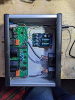
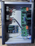
Well, I hand built/soldered the panel version and placed it in a Hammond casing. I don't have any components that actually use Balanced connections but wanted to be able to go from SE to Balanced (probably to try amps like the Purifi variety) somewhere in the future. Guess I won't know if it actually works correctly until I get a Balanced in amp?
Cheers
Pete
Cheers
Pete
Attachments

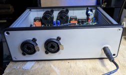
Nice work Pete! You will soon find how handy this box is once you have balanced gear. It’s also handy for balanced preamps outs. They can run longer distances without less noise pickup and then drive SE input amps.
- Home
- Group Buys
- BTSB Buffer - SE/Bal to SE/Bal Buffer GB