My question was referring to the signal, not power rails.
I guess the max signal output will nevertheless be limited by to rails so < 28 Vpp (for +/- 14V).
I guess the max signal output will nevertheless be limited by to rails so < 28 Vpp (for +/- 14V).
Today is your lucky day. If you are using the balanced output of the LME49724, because it is a fully differential output driver, with +/-18v rails, it can achieve an output swing of 52Vpp! Scaling by 15/18 we get 42Vpp. This is actually news to me and it means you aren’t ever going to run into clipping issues from the buffer if you use the balanced output drive. Come to think of it, that’s enough to drive 0dB power amps like F4 to full power (40Vpp for 25W into 8ohms).
Wow!
Here is datasheet on LME49724:
https://www.ti.com/lit/ds/symlink/l...16344&ref_url=https%3A%2F%2Fwww.mouser.com%2F
If you use the single ended output, the OPA1656 is able to go to within 275mV of rail before clipping.
So +/- 14.7V or 29.45Vpp.
Wow!
Here is datasheet on LME49724:
https://www.ti.com/lit/ds/symlink/l...16344&ref_url=https%3A%2F%2Fwww.mouser.com%2F
If you use the single ended output, the OPA1656 is able to go to within 275mV of rail before clipping.
So +/- 14.7V or 29.45Vpp.
Sounds very good! I might well try this out.
As I will principally be using it for testing of power followers I need to know the bandwidth. Is this limited by LME49729 or is there a low-pass filter in the circuit?
As I will principally be using it for testing of power followers I need to know the bandwidth. Is this limited by LME49729 or is there a low-pass filter in the circuit?
I think there is a 470pF in series with 100pF to ground as input filter. There is a 121R input series resistor with equivalent 87pF cap for -3dB RC filter of 15MHz low pass. Jhofland can correct me if I am wrong in these calcs but you should be good for most any audio application.


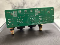
Before:

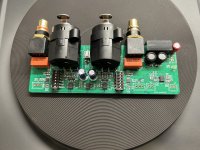
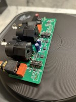
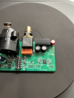
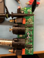
After attached below 👇.
My heartfelt thanks to jhofland, xrk971, etc…
This was definitely easier than the Headphone SSR protection! So much more space!
Time to test on the scope!
Best,
Anand.
After attached below 👇.
My heartfelt thanks to jhofland, xrk971, etc…
This was definitely easier than the Headphone SSR protection! So much more space!
Time to test on the scope!
Best,
Anand.
Attachments
Last edited:
Nice work, Anand! You are becoming a natural SMT’er.
You will love the sound and how handy these are. Convert any source to suit any amp.
Congrats.
You will love the sound and how handy these are. Convert any source to suit any amp.
Congrats.
As much as I find your RTR versions a time savor, the satisfaction simple isn’t there! SMT is cathartic and really not hard at all. The tools needed cost well under $100 and my speed on this build was much faster than the headphone SSR protection board. This was partly because a majority of the parts on the rear of this board are the same values. I thought about a stencil but honestly, if you prewarm the board to about 100 degC with hot air, then the syringe with your 22 AWG nozzles dispense the solder paste at approximately 1 dot/sec. So you feel like a baker in a bakery. Reminds me of the pipets I used when I was a research student at NCI/Bethesda. Every drop of solder paste was precise and timed.Nice work, Anand! You are becoming a natural SMT’er.
You will love the sound and how handy these are. Convert any source to suit any amp.
Congrats.
I have done SMT several times before, but my last major SMT build was the Starkrimson and previous to that it was the Neurochrome Modulus 286 v1.1 which I did solely with a soldering iron.
This method today with hot air was demonstrably faster and better looking to boot. The unit above will be at the front end of my FH9HVX build.
Best,
Anand.
Awesome work Anand!
Each build increases confidence with SMT work, you'll be attempting DFN-8 packages before you know it
Each build increases confidence with SMT work, you'll be attempting DFN-8 packages before you know it
Hi Anand,
Cathartic and fun when small projects like this. When you hit 300 components it’s not as fun especially when each part and location is not easily found but like a game of “can you find the deer hidden in the zoo park” type picture puzzles, 300 times.
Cathartic and fun when small projects like this. When you hit 300 components it’s not as fun especially when each part and location is not easily found but like a game of “can you find the deer hidden in the zoo park” type picture puzzles, 300 times.
Fellas,
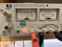
Bode plot from my Keysight scope of one of the channels on this BTSB board. I set the dip switches for “0” dB gain for easy visuals. All the other settings (-6, 0, +8, +14 dB) look the same - recall I did the (-6dB) modification by altering resistors R33-R36 to 2K49. Bode plot shows -3dB @ 125khz from the unbalanced output. Phase is flat to about 20khz, -25 degrees @ 40khz, -60 degrees @ 100khz. Used my HP6237B bench supply to set it to 12VDC. The board draws about 100mA of current.
Best,
Anand.
Attachments
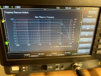
Nice tools! I never had an automatic Bode plot thingamajig… 🙂
The phase is probably a function of the input EMI / RFI filter network. If those are removed it would be much higher. Although flat to 20kHz should be fine for most folks.
The phase is probably a function of the input EMI / RFI filter network. If those are removed it would be much higher. Although flat to 20kHz should be fine for most folks.
I was wondering if you had given any thought to a single channel BTSB. I guess I could always just not populate one of the channels on the dual unit. Since I am building mono-blocks mostly, just thought I should ask.
So if you are putting this in an amp, where are you getting the 12V from for the BTSB?
Regulate the DC voltage to the amps, 12V meanwell SMPS off the mains, or a separate transformer ( or different winding from the main transformer) to a regulator board?
Regulate the DC voltage to the amps, 12V meanwell SMPS off the mains, or a separate transformer ( or different winding from the main transformer) to a regulator board?
Both are correct. Whether you do a small bridge rectifier, capacitor then regulator like an AMB Sigma 25 or a switcher supply is immaterial. All you need to know is the current requirement is well below 1A. In fact 0.5A should be plenty including transients. If doing the linear supply option, you can use a separate winding from your main transformer (if available) or use a completely separate and small transformer (like 5VA in size).So if you are putting this in an amp, where are you getting the 12V from for the BTSB?
Regulate the DC voltage to the amps, 12V meanwell SMPS off the mains, or a separate transformer ( or different winding from the main transformer) to a regulator board?
Best,
Anand.
Both are correct. Whether you do a small bridge rectifier, capacitor then regulator like an AMB Sigma 25 or a switcher supply is immaterial. All you need to know is the current requirement is well below 1A. In fact 0.5A should be plenty including transients. If doing the linear supply option, you can use a separate winding from your main transformer (if available) or use a completely separate and small transformer (like 5VA in size).
Best,
Anand.
Just double checking, I will confirm here that the actual current draw (on the DC side) is about 150mA for this circuit, not 100mA as I stated in post 352. So as long as you have a power supply that is comfortably capable of 12V DC and at least 150mA (I would go to 200mA to address transients) you should be fine.
Best,
Anand.
I think the on board DCDC converter is rated at 70mA per rail so 140mA at 15v and so conservation of energy is 15v/12vx140mA and divide by circa 0.9 efficiency for 194mA at 12v. But that’s assuming you want or need full output power. As a preamp, it would generally not be needed to drive that much current into the outputs. I generally use an external 1000mA 12vdc wall wart or a linear supply with LM7812 regulator capable of 1A to be on the safe side. I think plan for 250mA at 12v and you should be safe.
X,I think the on board DCDC converter is rated at 70mA per rail so 140mA at 15v and so conservation of energy is 15v/12vx140mA and divide by circa 0.9 efficiency for 194mA at 12v. But that’s assuming you want or need full output power. As a preamp, it would generally not be needed to drive that much current into the outputs. I generally use an external 1000mA 12vdc wall wart or a linear supply with LM7812 regulator capable of 1A to be on the safe side. I think plan for 250mA at 12v and you should be safe.
Great advice. Yes, 0.9 efficiency for a capacitor input supply is the best case scenario. I’ve seen it as low as 0.6-0.7 as well (when driven hard and accounting for losses).
Since I am custom ordering a transformer for my FH9HVX build (400VA with 40V secondaries), my plan was to have them add an additional 12V secondary @ 0.5A to 1A which I can plug into the AMB Sigma 25 supply board (with sigma 78 regulator I have). They should easily be able to accommodate the additional 6VA to 12VA to the existing 400VA core.
Best,
Anand.
- Home
- Group Buys
- BTSB Buffer - SE/Bal to SE/Bal Buffer GB