I just ran same test with BTSB Panel Mount that uses OPA1637 balanced line driver.
Same result - works fine and delivers about same 48.8Vpp with 4.9Vpp input.

Small glitch on O-scope probably due to function Generator in O-scope being driven too hard. Lowering it to get exactly 40Vpp gives nice trace:


Fluke TrueRMS DMM shows 17.30Vrms or 48.95Vpp.
So I think we are good to go with either version being able to drive and F4 to 40Vpp.
That tiny OPA1637 is an impressive little chip! 3mm x 3mm 8 pin VSSOP format.
Same result - works fine and delivers about same 48.8Vpp with 4.9Vpp input.
Small glitch on O-scope probably due to function Generator in O-scope being driven too hard. Lowering it to get exactly 40Vpp gives nice trace:
Fluke TrueRMS DMM shows 17.30Vrms or 48.95Vpp.
So I think we are good to go with either version being able to drive and F4 to 40Vpp.
That tiny OPA1637 is an impressive little chip! 3mm x 3mm 8 pin VSSOP format.
Last edited:
There is not an 18v version of DPAN02 DCDC. You can use external +/-18v but that’s running right at limit of part.
Are you trying to get more than 40Vpp?
I have a HV opamp board that uses the M2X/Yarra format.
150Vpp with 30mA capability. Depending on your rails. The one I have has built in +/-35v PSU DCDC converter. So should have 70Vpp swing (SE).
https://www.diyaudio.com/community/threads/opa454-front-end-for-lufo-amp.373243/#post-7104704


You can also use external PSU like above.
I used this on SuSyLu amp which is balanced 100W class A. In balanced mode +/-35v rails gives 70Vpp single ended - so should be able to hit 140Vpp in balanced output. 100w amp needs 80Vpp balanced output.

Are you trying to get more than 40Vpp?
I have a HV opamp board that uses the M2X/Yarra format.
150Vpp with 30mA capability. Depending on your rails. The one I have has built in +/-35v PSU DCDC converter. So should have 70Vpp swing (SE).
https://www.diyaudio.com/community/threads/opa454-front-end-for-lufo-amp.373243/#post-7104704
You can also use external PSU like above.
I used this on SuSyLu amp which is balanced 100W class A. In balanced mode +/-35v rails gives 70Vpp single ended - so should be able to hit 140Vpp in balanced output. 100w amp needs 80Vpp balanced output.
Last edited:
X,
I was just curious with regards to +/- 18V…no worries.
Yes, I remember LuFo … fun build if you can get the right choke!
Best,
Anand.
I was just curious with regards to +/- 18V…no worries.
Yes, I remember LuFo … fun build if you can get the right choke!
Best,
Anand.
The PCB itself is 132mm wide x 45mm deep as stated in Post #1. The dimensions of the rear panel cutout holes for the output jacks is in this thread Post #1 and also in my shop. I am reposting below. But note that the CTC vertical distance is actually 7.25mm as the RCA jacks that I am using are a little different than the Elecaudio's that were used in the orginal. If you buid your own with Elecaudio jacks then the 8.25mm distance is correct.

Last edited:

Thanks. I checked both of the BTSB Panel mount threads and it wasn't there. I guess I should have checked this thread also. I am building tall monoblocks with a backpanel of 150mm. Just checking to see if these will fit prior to ordering.
My own concept.
A monoblock with 2 4U x 300 heat sinks each. Wolverine on one heat sink and FH9HVX on the other. BTSB or THAT RXR on back to go from XLR to SE that the amps need. I will use the AllCees PSU in each Monoblock. I will use some modushop parts: MiniD base plate, heatsinks and brackets, Diss 4U backpanels rotated 90 degrees for the rear panel, Diss 5U backpanels for the front panel, 150mm MiniD tops and bottoms. The PSU and transformers will be mounted below the heatsinks. So it would be roughly 230 mm wide x 350 mm tall. The sides of the PSU area will be constructed of wood as well as the decorative front panel. I will be running active 2 way speakers using DIYAudio store active crossover with two BTSBs on the output so to get balanced XLR outputs. My sources are located on the opposite side of the room from the speakers so I decided to use XLR connections for all my amps. I have a little more than 4' between speakers to place amps. So I can get 4 amps in that space without stacking.
Not sure yet if I will hook up both amp boards at the same time or not. I will need to test it out. Plan to use a 400va transformer with 2x40Vac secondaries. 100W or so should be fine.
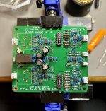
Only my second time doing SMD work and it’s just as miraculous as the first. I was convinced it wouldn’t work out and magically I ended up with nice shiny joints. I used the hot plate plus hot air rework station method.
Since this is a 1.2 TH board, I’m expecting to cross R42 and R43. Is that correct?
Since this is a 1.2 TH board, I’m expecting to cross R42 and R43. Is that correct?
Attachments
Fantastic work von Ah!
Look over the joints with eye magnification and check for the tiny solder “balls”, hit them with a fine tipped iron or you can just pick them off with tweezers.
Look over the joints with eye magnification and check for the tiny solder “balls”, hit them with a fine tipped iron or you can just pick them off with tweezers.
Thanks, Vunce! I did just that after they were soldered in. Picked off one solder ball and some flux gunk between pins. 😎
Even the ‘no clean’ paste needs to be cleaned with Iso afterwards.
Perfect!

Perfect!
Does the BTSB need a load in order to power up? My unit won’t measure 12VDC at the power input when it’s connected. It cycles from 200-800 mV when 12VDC is applied.
No load needed to power up. Are you sure you have polarity correct on the input?
The output is +/-15v and you measure that at the three output pins relative to the middle output pin. The input 12v and GND is isolated by 5200v from the outputs. make sure the DMM lead for -ve is not relative to the PSU GND but to the output GND.
Here is a closeup of the connections and where to check. I may have the +ve and -ve output mixed up but main thing is to measure output voltage relative to the middle pin.

ISO means galvanic isolation barrier.
The output is +/-15v and you measure that at the three output pins relative to the middle output pin. The input 12v and GND is isolated by 5200v from the outputs. make sure the DMM lead for -ve is not relative to the PSU GND but to the output GND.
Here is a closeup of the connections and where to check. I may have the +ve and -ve output mixed up but main thing is to measure output voltage relative to the middle pin.
ISO means galvanic isolation barrier.
Last edited:
I am in need of a SE to Balanced buffer for my phono preamp outputs. Can this work for that use case? I have essential tremor in both hands so soldering through hole components is quite difficult, but possible. I suspect that SMD soldering would be out of the question for me. Could I purchase either with the SMD parts already soldered or RTR?
Last edited:
- Home
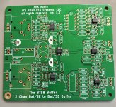
- Group Buys
- BTSB Buffer - SE/Bal to SE/Bal Buffer GB