Thanks, I'll check the R39. And it is also stored at an angle. What temperature do you have set when using SMDLTLFP? I had heated the PCB to 120°C. I used an old clothes iron. Thank you for your reply.
If your solder is PbFree try 360C, if 60/40 Pb/Sn then try 320C.
Use some flux and the surface tension of the melted solder will align the chip resistor. You could just leave it as it is as it is mostly a cosmetic issue.
Practice with a scrap PCBA to develop your skills. Using the iron underneath is a good idea but not necessarily needed as there isn't too much additional thermal load to heat; that is, copper etc.
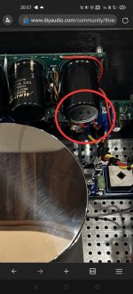
That looks like a good solder joint. Just cosmetically misaligned but should work. It’s quite clean - free of small solder balls etc. what brand solder paste are you using?
Oh, it's a low temp alloy... Sn42/Bi57.6/Ag0.4, melting point 138C
Recommended reflow temperature is 165C
Recommended reflow temperature is 165C
These data are in the technical documentation. I am interested in the practical setting of the hot air station. I had to have about 200°C to work well with this paste.

fnirsi-dso-tc3-3-in-1-digital-oscilloscope
I'm asking for advice. Do you think that for the price of 45 euros it is a good thing? Does it have the necessary features? I need it mainly as a do-it-yourself oscilloscope. The last time I worked on the Oscilloscope was when I was studying at an electronics school. r: 1986.
I'm asking for advice. Do you think that for the price of 45 euros it is a good thing? Does it have the necessary features? I need it mainly as a do-it-yourself oscilloscope. The last time I worked on the Oscilloscope was when I was studying at an electronics school. r: 1986.
Last edited:
Happy update!
I was bummed I couldn’t figure out what was causing trouble with my board and really didn’t relish the idea of taking measurements at every point, so this project sat idle for a while.
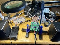
Jut now decided to give it another look under magnification. One end of the Murata solder joints looked a bit off, so I removed that pin’s solder and resoldered it. Eureka! Everything works! I’m not a failure after all.
Now I have two of these working well, one in an enclosure and one as a free board. This makes me happy.
I was bummed I couldn’t figure out what was causing trouble with my board and really didn’t relish the idea of taking measurements at every point, so this project sat idle for a while.
Jut now decided to give it another look under magnification. One end of the Murata solder joints looked a bit off, so I removed that pin’s solder and resoldered it. Eureka! Everything works! I’m not a failure after all.
Now I have two of these working well, one in an enclosure and one as a free board. This makes me happy.
Attachments
Last edited:
My current ideas for use are the TDV and the LU1014D OPS I luckily won from schultzsch. Those are the no-voltage-gain amps I have currently. I also have a M2 OPS build brewing in my mind.
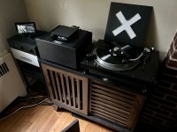
The one in the enclosure I use for my vinyl rig when needed between my phono pre and whatever else is next (ADC or analog preamp).
The one in the enclosure I use for my vinyl rig when needed between my phono pre and whatever else is next (ADC or analog preamp).
I would love to see what kinds of projects folks who have built this board are using it in. Please share photos of you can.
Do,
Thanks! Big compliment from a builder whose builds are super neat and tidy!
It’s a Vcap ODAM with Miflex copper bypass.
Best,
Anand.
Thanks! Big compliment from a builder whose builds are super neat and tidy!
It’s a Vcap ODAM with Miflex copper bypass.
Best,
Anand.
Hi Folks,
Anand has pointed out that the BTSB (all variants) will have a turnoff pop if they are powered off before the amp rails are fully discharged. This is due to an asymmetric collapse of the +/- rails of the +/-15v DCDC supply that is on board. This is well known and in most cases, not an issue as we always power off the power amp before powering off the preamp. It’s the same as not hot plugging in an RCA or XLR while a preamp is connected to a power amp and speakers.
If you are using the Panel Mount BTSB as an integral part of an amplifier- please make sure you either have a way of providing 12v power for the BTSB first before the amp turns on and keep it on until the power amp turns off. If using as buffer for TPA3255, it’s simple enough to add a 2200uF 16v rail cap to the 12v power in connector somewhere. This keeps the BTSB on until after the amp powers off via decay.
If using with a linear PSU with very large capacitances, the easy way to prevent pop is to leave the BTSB always powered on or use a speaker protection SSR with the instant off feature (either via logic control or low capacitance PSU as provided with my RTR SSR speaker protection boards). These will have a 2 second delay when turning on and turn off in about 10ms to ensure that there is no speaker pop.
In any case, my recommendation and easy lazy way to prevent pop from the BTSB is to keep it powered always on.
In case you wonder why I don’t have a SSR to disable the BTSB outputs to prevent pop - there are 6 outputs that would need a relay and that adds significant cost and complexity to what is a simple circuit that is meant to do one thing well: convert SE/Bal to SE and Bal while providing selectable gain with a simple PSU.
Hope this helps.
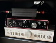
Here is a polar opposite photo to Anand’s. It’s just a black box with my BTSB in it.I would love to see what kinds of projects folks who have built this board are using it in. Please share photos of you can.

I use it to boost the MM phono output of my vinyl setup. The setup currently consists of:
- Technics SL-1100 table
- Pickering XUV cart (LPGear D4500Q replacement stylus)
- Toshiba SY-C15 Preamp (Phono input to tape out)
- BTSB (set at max gain)
- Focusrite Scarlett 8i6 (for ADC)
- MiniDSP Flex Eight (for DSP PEQ)
- Zen Mod Iron Pre SE (for Fugly goodness)
- Zen Mod Scryer amp (for even more Fugly goodness)
- DIY open baffle 3-way speakers
Attachments
Here's my current implementation of the BTSB. Parts are..

Let's say I am interested in something like that, do you happen to have a schematic available? I don't mind designing my own boards, but I don't know that I could pioneer a circuit along the lines of your SSR headphone protection or something.
- Modushop Slimline 2u 280mm deep, fully vented top
- 2x Connex Electronic SMPS600RS
- 2x Sylph Audio D400M TPA3255 boards
- BTSB w/ 6800uF PSU capacitor to keep it online past amp decay
In case you wonder why I don’t have a SSR to disable the BTSB outputs to prevent pop - there are 6 outputs that would need a relay and that adds significant cost and complexity to what is a simple circuit that is meant to do one thing well: convert SE/Bal to SE and Bal while providing selectable gain with a simple PSU.
Let's say I am interested in something like that, do you happen to have a schematic available? I don't mind designing my own boards, but I don't know that I could pioneer a circuit along the lines of your SSR headphone protection or something.
- Home
- Group Buys
- BTSB Buffer - SE/Bal to SE/Bal Buffer GB