Yes, nice work.
Great to be able to custom design and make your own case - no sawdust required!
Great to be able to custom design and make your own case - no sawdust required!
Last edited:
Thanks. Yes I crossed the resistors and put them on the underside of the board.
Nice. Sneaky fix there. 🙂
Drilling inaccurate holes is a thing of the past but drawing inaccurate holes in CAD is still a problem that has bitten me more than a few times.
I made a 3d printed case for the TH BTSB. As XRK mentioned a very handy accessory to have on hand for connecting almost any source to any amplifier.
As finding a good quality case and drilling it can often be harder than doing the board, I would love to be able to save that precious time and use this case.
Especially because I need/ want several BTSBs
Wineds,
By sharing that zip file - am I right that you don’t mind others using your CAD file?
<< for a 3D printer - I’ve got several, non hifi projects in mind, though they are design from scratch projects which are a bit of a way off needing a printer.… premature to look into & buy a printer. (The little I’d done a year ago had your choice of brand Prussa looking promising) >>
But - it just occurred to me I could simply find a 3-D commercial service.
Just now I can’t open zip files. I’m guessing it’s ~ 130 * 100 * 65 mm, and ? 3 mm thick. And in a file format that’s reasonably standard?
Hi Otto,
I can also provide the 3d print file for the BTSB panel mount version. You can then mount that panel on a box of your choice.
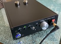
Another way we can do this is to have me make custom PCBs as front and rear panels that will fit a standard Hammond case. That’s what Jhofland has been doing to make front and rear panels for our prototype headphone amps. They can even be covered with copper for RF shielding as they are PCBs. I just saw today that JLCPB is offering aluminum PCBs for $2 and will drill holes as small as 1mm. Now that might be an interesting option as wel.
Here’s an example of how a PCB can be made to have holes and lettering for a Hammond case. This is a hybrid tube/SS headphone amp capable of 5w into 32ohms that we have been working on:

I can also provide the 3d print file for the BTSB panel mount version. You can then mount that panel on a box of your choice.
Another way we can do this is to have me make custom PCBs as front and rear panels that will fit a standard Hammond case. That’s what Jhofland has been doing to make front and rear panels for our prototype headphone amps. They can even be covered with copper for RF shielding as they are PCBs. I just saw today that JLCPB is offering aluminum PCBs for $2 and will drill holes as small as 1mm. Now that might be an interesting option as wel.
Here’s an example of how a PCB can be made to have holes and lettering for a Hammond case. This is a hybrid tube/SS headphone amp capable of 5w into 32ohms that we have been working on:
Attachments
Last edited:
As finding a good quality case and drilling it can often be harder than doing the board, I would love to be able to save that precious time and use this case.
Especially because I need/ want several BTSBs
Wineds,
By sharing that zip file - am I right that you don’t mind others using your CAD file?
<< for a 3D printer - I’ve got several, non hifi projects in mind, though they are design from scratch projects which are a bit of a way off needing a printer.… premature to look into & buy a printer. (The little I’d done a year ago had your choice of brand Prussa looking promising) >>
But - it just occurred to me I could simply find a 3-D commercial service.
Just now I can’t open zip files. I’m guessing it’s ~ 130 * 100 * 65 mm, and ? 3 mm thick. And in a file format that’s reasonably standard?
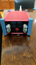
Yes happy for anyone to use it. Files are stl which is a common standard. 3d builder which is part of windows can open them.
BTW the TPA 3255 case of coming along nicely.
Attachments
Last edited:
I made a 3d printed case for the TH BTSB. As XRK mentioned a very handy accessory to have on hand for connecting almost any source to any amplifier.
Love the case and wish I had a 3D Printer !!
When you soldered up the board did you manage to solder the pads on the Balanced Driver ICs as well as the pins ? I am just worried about cooking the IC !!
To solder chips with belly thermal pads (LME49724 or OPA1656 etc) s l as it’s best to use solder paste and hot air. You could use paste and iron if you apply a large chisel tip iron to the vias beneath the belly pad. Still use solder paste. The chips are pretty rugged if you only heat them for under 10 seconds to temps that melt solder. If you use low temp solder (165C) that’s even safer.
Last edited:
Hi Folks,
I am just throwing this idea out to see if there is enough interest. I am considering offering the BTSB Panel Mount as fully assembled, tested and ready to run for $165 ea. Board will include XLR/TRS jacks (non locking) and RCA jacks. You need to provide your own 12vdc PSU like a wall wart, etc.
I am just throwing this idea out to see if there is enough interest. I am considering offering the BTSB Panel Mount as fully assembled, tested and ready to run for $165 ea. Board will include XLR/TRS jacks (non locking) and RCA jacks. You need to provide your own 12vdc PSU like a wall wart, etc.
Ok, this is surprising that there isn’t any interest in a RTR panel mount BTSB for only $50 more than it would cost for you to buy and build yourself.
I guess the DIY assembly required aspect is not so bad.
I guess the DIY assembly required aspect is not so bad.
Hi,
I have some questions:
I have some questions:
- I just need a few balanced-to-single-ended converters, each for two channels. So, can I omit the balanced line drivers at the output?
- Doug Self talks about how the conventional single op-amp balanced input circuit has a lot more noise than a single-ended input voltage follower, because of the Johnson noise of the resistors. We are not using any of his four-opamp and eight-opamp designs to cut the noise, yet we are getting pretty low noise. How is this happening? Is this because we use newer opamps than his NE5532?
- Can I get the TH version with the SMD parts soldered on?
- Can the TH board "hang off" the panel-mounted XLR sockets safely? Or will support be necessary on the mounting holes?
The TH panel can be mounted from just the XLR jacks. It should be strong enough. I used to offer the SMT parts presoldered but too hard to find them lately so I can’t offer it. You can leave balanced driver off if not needed. Or leave SE out if not needed.
Why is it low noise? NE5532 is a good part but is all BJT technology. I think the OPA1656 has MOSFET inputs. OPA1642 can also be used and is even quieter with JFET inputs. I’m not sure the noise of the NE5532 is that audible is it?
These are SOIC8 components with exposed legs. Very easy to hand solder with conventional iron. Try using solder paste on pads and then touching with regular iron tip. That works well as it has flux built in.
Thanks for all the answers, XRK.

In the schematic, it seems that the inputs of the U7B opamp are coming from the balanced line driver outputs just before R41 and R42. So if I omit the balanced line driver chip, will the U7B work? Or will the signal reach U7B via R33 and R35?
The book illustrates the impact of the input stage noise on the overall power amp noise through this table:

He then goes to design multi-opamp balanced inputs which really cut down the noise of the input stage. He explores other low-noise opamps too, beyond the NE5532. He also has such an input stage on his website: http://www.signaltransfer.freeuk.com/lownoisebal.htm
I was wondering how we are getting low noise in our balanced input circuit without all these techniques.
Hope I'm making sense?
Cool.The TH panel can be mounted from just the XLR jacks. It should be strong enough.
Ok, I'll figure this out if I go for this option.I used to offer the SMT parts presoldered but too hard to find them lately so I can’t offer it.
My doubt comes from the output stage of the circuit:You can leave balanced driver off if not needed. Or leave SE out if not needed.
In the schematic, it seems that the inputs of the U7B opamp are coming from the balanced line driver outputs just before R41 and R42. So if I omit the balanced line driver chip, will the U7B work? Or will the signal reach U7B via R33 and R35?
I'm no expert. 🙁 I was just referring to what I've read in Doug Self's books. If you see his Audio Power Amplifier Design Handbook (5/ed, 6/ed, take your pick), you'll find a chapter which talks about input circuits, and there he discussed balanced input circuits. He first shows a balanced circuit with just one opamp and passives, and then says that this is far worse than a single-ended input with one opamp. In his words, "the noise output of a 4 x 10 k balanced input amp using an NE5532 is -105.1 dBu, which completely swamps the power amplifier EIN and degrades the overall noise performance by 17.5 dB."Why is it low noise? NE5532 is a good part but is all BJT technology. I think the OPA1656 has MOSFET inputs. OPA1642 can also be used and is even quieter with JFET inputs. I’m not sure the noise of the NE5532 is that audible is it?
The book illustrates the impact of the input stage noise on the overall power amp noise through this table:
He then goes to design multi-opamp balanced inputs which really cut down the noise of the input stage. He explores other low-noise opamps too, beyond the NE5532. He also has such an input stage on his website: http://www.signaltransfer.freeuk.com/lownoisebal.htm
I was wondering how we are getting low noise in our balanced input circuit without all these techniques.
Hope I'm making sense?
Oops, my bad. Forgot that the SE depends on balanced output. So no, you cannot leave off balanced drive opamp. Sorry about that.
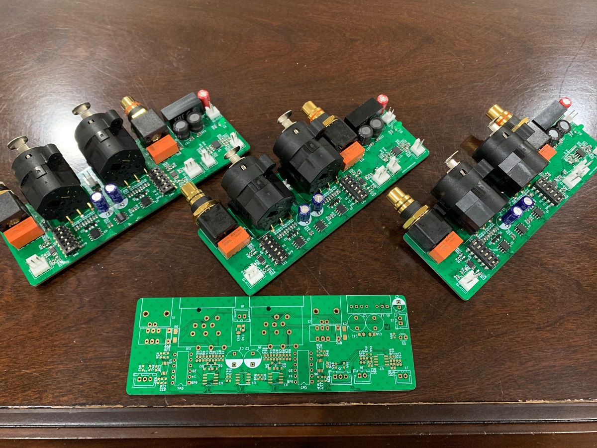
Finished up a collection of panel mounts today. Happy to be done. That’s a lot of soldering under a magnifier! I’ll do a separate write up of the process I followed when I get some more time.


Sweet work Chris! Your lucky to be able to assemble these with the worldwide parts shortage. Very handy board to have 👍
Thanks! I’ve had parts since last summer but had other projects to do. Finally got to it a couple weeks ago. They’ll be part of an upcoming project where they should be super useful.Sweet work Chris! Your lucky to be able to assemble these with the worldwide parts shortage. Very handy board to have 👍
Learned a lot new techniques building these. Had to be super careful making sure all the parts went in the right spots!
- Home
- Group Buys
- BTSB Buffer - SE/Bal to SE/Bal Buffer GB