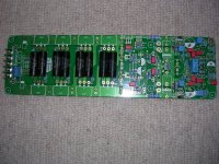
Bryston input board
Hello again.
I decided to put my input board for the Bryston 4bsst up for sale, I want to use external buffer amp, and experiment with both discrete and chip .
The board is populated only with quality parts.
You can find it in swap meet, I also have most parts for a complete new build if anyone should get the urge.
Thomas
Attachments

Some progress at last! Getting on with the power amp modules. I tend to review each component as I insert it into the pcb and I've come up with a couple of things. The "real" Bryston is dc coupled but the "clone" has 10uf ( standard electrolytic ) dc input blocking capacitor at the input. Not a problem if the capacitor has the right value and is of the right type. However both the Bryston and its clone power amp module have a very low input impedance ( 1k ) and are intended to be paired with a high current drive input module. No problem with the dc coupled Bryston; but the 10uf capacitor and the 1k input impedance of the clone lead to the voltage output of the amplifier module being 6dB down at 12.5Hz. This is a bit too high for me so I use a 100uf bipolar to reduce the lf rolloff to well below audible frequencies and reduce the distortion. I also use a 2200uF 16V bipolar electrolytic in the feedback path instead of the standard electrolytic in the BOM.
New builders should note that the PN100A/PN200A small signal transistors used in the input and power amp modules are now obsolete and pure unobtainium from the major distributors. Fortunately the BC546/BC556 are a good substitute as long as you remember to put them in backwards; the leads run cbe rather than ebc. The BC546B/BC556B ( hfe 200-450 ) are readily available, but the more desirable BC546C/BC556C ( hfe 420-800 ) less so because the major manufacturers no longer produce the C variant. Fortunately Diotec still manufacture the BC546C/BC556C and can be found if you shop around.
This may be a blessing in disguise because the PN100A/PN200A have a lower hfe range ( 300-600 ) and a lower Vceo ( 45V vs 65V ) than the BC546C/BC556C. Notice that a PN100A/PN200A pair are used as a complementary VAS in the input module discrete opamp, in both the Bryston and the clone, running off of +/-33V supply rails! I wouldn't test the clone input module by itself at full output for any length of time! Not a problem with the BC546C/BC556C pair.
The matching between PN100A and PN200A seems to be a bit of a problem - In my case one set of hfe is clustered around 300 and the other around 400. Not ideal. I'm waiting for my BC546C/BC556C to arrive and if the matching is better I'll replace the PN100A/PN200A in my input modules with BC546C/BC556C and lso use them for the input LTPs of the power amp module.
Finally I used 1% 1W metal film resistors for R14 and R38-41 rather than the 0.25W and 0.5W listed in the BOM.
Attachments
Diotec BC546C/BC556C arrived today. I sampled 12 of each and both types have hfe in the range 480-530. Looks like I'll be able to get perfect matches for all of my Bryston clone pcbs. Yippee!!! Haven't checked the Vceo yet but will do so today and report back. I got the devices from V&U Electronic Components in the UK, but Diotec have distributors in most EU countries and the US so availablity shouldn't be a problem.
Vceo measures 75V for the npn and 95V for the pnp parts, so they appear to be generously specced. Definitely be using these rather than the PN100A/PN200A.
Voltages are measured at a specific leakage current level, so constant current source or sink and high voltage supply perhaps?
Nah, DUOYI DY294 Digital Transistor DC parameter tester from ebay for about £38 GBP. Leakage current <1ma
How is the bias spreader thermal sensing done on that clone? Exact same as the real bryston? One TO92 and one TO126? The TO126 mounted on the heatsink just like the rest of it?
Any photos with such details?
What bias current ended up being adequate? 25-50mA or so?
Any photos with such details?
What bias current ended up being adequate? 25-50mA or so?
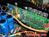
Yes its done in exactly the same way as in the Bryston amps proper. You can see the to92 at the top middle of the pcb next to the blue trimpot. The T0126 is vertically below the to92, bolted to the heatsink with a stainless steel capscrew ( its the leftmost one ). Don't know about bias current as I haven't quite finished my power amp boards yet. If Amplitude drops by he'll let you know as his amp is finished and working.
Attachments
Forgot to mention; my BC546C/BC556C turned up a day or two ago and both the pnp and npn parts have hfes clustered very close to 500 - Result! I'm really pleased with that. I also have batches of closely matched 2N5401/2N5551 which are also used in this amp.
Yes its done in exactly the same way as in the Bryston amps proper. You can see the to92 at the top middle of the pcb next to the blue trimpot. The T0126 is vertically below the to92, bolted to the heatsink with a stainless steel capscrew ( its the leftmost one ).
Are you certain you're pointing at the right one(s)?
It would make sense for the trimpot to be very close to the to92 bias tranny, and it would also make a lot of sense if the other bias tranny wasn't overly far from that. But from what I can see, the TO220 that is near this, is also right next to the outputs, which would be one of the drivers (MJE1503x), and I don't see a to126 so close to the to92 and trimpot.
Now that to220 further on the left, near that big blue electro cap, isn't a to126, unless the mje180 was replaced by something else in to220, and it seems a little far away from the trimpot and to92... Weird!
It does make sense not to use the to92 for thermal sensing, mostly because it's awkward to mount properly for thermal contact, and that contact can never be that good anyway. It's not geared for that purpose, so it's much better to use a to126 properly mounted on the heatsink, for best thermal contact.
It seems there it a to92 very close to that to220 on the left side there near that big blue cap, but then no trimpot nearby, which hints at not being the thermal/bias stuff...
If we had a schematic to refer to, with part names, we could remove ambiguity and make sure we're looking at the right parts.
Don't know about bias current as I haven't quite finished my power amp boards yet. If Amplitude drops by he'll let you know as his amp is finished and working.
I recall having seen some bias setup info quite some time ago, and although I'm not certain, I think it was in the 25-50mA range (per output tranny).
But I think it's best to adjust that with a scope, at the bare minimum, and best with an analyzer and increase the bias until most distortion is gone.
Forgot to mention; my BC546C/BC556C turned up a day or two ago and both the pnp and npn parts have hfes clustered very close to 500 - Result! I'm really pleased with that. I also have batches of closely matched 2N5401/2N5551 which are also used in this amp.
Are you kidding??? ;-) that's outstanding!!! I'd be super happy to get such batches myself.
What did you use to check that? Do you also check for vbe?
Matching both the vbe AND hfe could be challenging.
But if you're starting with such a good batch with a lot of very similar hfe, it might not be overly hard to also match for vbe. That would be stupendous!
That's actually what I would aim for myself, along with matching resistors where needed, like the degen, mirrors, etc...
And while at it, matching the vas ones, drivers and all the outputs...
Might be much more tricky to get the outputs matched, unless you have the funds for a large enough batch to pick from...
The to92 ( 2N5551 ) is indeed at the top of the pcb next to the trimpot and the other half of the bias spreader is a to225 ( MJE182 ) on the other side of the pcb. Weird I know, but there you are.
The to92 ( 2N5551 ) is indeed at the top of the pcb next to the trimpot and the other half of the bias spreader is a to225 ( MJE182 ) on the other side of the pcb. Weird I know, but there you are.
Weird indeed. Why go so far away...
But I get it now, having poked around the blank pcbs and blown them up on screen hoping to see a little more. I see what was done with it, and the traces crossing that board to reach that other one on the board's other side...
I wonder what the motivation was for that far separation, but I see now how it was done.
So it confirms the fact that the to92 isn't used for thermo-sensing at all, and only that other one is doing it. I'll have to do some spice sims on this, to understand more how it really works.
I've been trying to decide for some time which architecture to use for a multi-amp design that I've been working on for year. At first I was totally set on using the leach amp as the base, but then I did a lot of spice sims and found so many other architectures even more promissing, including the bryston approach, which, let's face it, simulates with quite low thd.
The thing I was wary about was how they did the thermal sensing with the bias spreader, and I thought it was a bit complex and the uncertainty about how the to92 was being used made me think again.
But now I think my preference comes back to the bryston approach and I'm about to put together sims for a bridge like the 28b.
btw: when I get through developing my design, I'll share what I did, but it may not be quite for everyone, because I'm aiming for a "modular" approach, where 4 power amp modules plus a 4way xover will inhabit a single rack on wheels.
I wanted to shoot for a modular approach to be able to not only make it easier to do maintenance on any modules, which should be as easy as possible to remove and test outside of the rack, but also to be able to replace one module by an other that could be a different design, just in case..
I wanted to shoot for a modular approach to be able to not only make it easier to do maintenance on any modules, which should be as easy as possible to remove and test outside of the rack, but also to be able to replace one module by an other that could be a different design, just in case..
Modular approach is a good idea - enables you to experiment with different part of the amp in isolation. The only thing I'd change is the configuration of the discrete component opamps ( DO33 ) used on the input and poweramp modules. This DO33 opamp has no degeneration of the complementary differential input stage and the push-pull vas stage consists of a single pair of complementary transistors. I'd go for input transistor degeneration and complementary darlington pairs for the push-pull vas. Should give lower hf distortion than the original. Notice that Bryston get their very low distortion figures because all of the complementary transistors are closely matched - an option not open to us. Still the measurements that amplitude made on his completed amps shows respectably low distortion.
DO33 opamp has no degeneration of the complementary differential input stage and the push-pull vas stage consists of a single pair of complementary transistors.
I agree. I've done quite a few spice sims on that and tried out a few "improvements" to figure out what could actually bring something extra.
At the very least I would add current sources for the ltp tails, and the degen as well. There might also be a benefit to cascoding the ltp. Current mirrors also seem like a good idea but many have said it may not give the best sonics, even though it would simulate better... Something to be experimenting with..
I'd go for input transistor degeneration and complementary darlington pairs for the push-pull vas.
That's "enhanced vas" as Self calls it. Maybe a thing to compare in sims... The degens are a must, at least for lower TIM for sure.
Should give lower hf distortion than the original.
It's pretty damn good already as it is, so although we may get some improvements, it won't be a huge one.
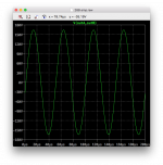
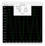
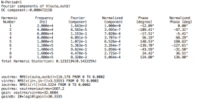
I'm playing with a full bridge right now of the 28BSST2 in sim, and it's doing great even at 20khz, with lower than 20ppm thd at some 1kw of power output on 8ohms resistive. With the rails set at 92V (unloaded) as they are on the real thing, with their 2kVA toroidal giving 2x65V...
And I just pushed it some more, not clipping yet, and although thd has increased to a little more than 0.12% (still 8ohms res load), we're talking about nearly 1.7kW output power. Must not be very far from clipping though, which would explain the rising thd...
Attaching some screenshots of the output..
Notice that Bryston get their very low distortion figures because all of the complementary transistors are closely matched - an option not open to us. Still the measurements that amplitude made on his completed amps shows respectably low distortion.
"option not open to us"???? I'm not going for that. I definitely will make all efforts possible to do all the feasible parts matching.
It's not overly hard to match the input pairs for the ltps in all the doas, amp diff stages and while at it, do all the vas and drivers.
Plus the outputs really need to be matched as well, as close as possible. This obviously can turn out expensive, because the batches of parts need to be large enough to hope to find enough sets. But when building many amp modules, there will be a need for a serious bunch of parts anyways, so might as well indulge a bit...
The ltps should be matched for both the vbe and hfe.
And I plan to do the pcb layout with the ltps flat faces against each other, so they can be pressed together (thermal paste) and tightly tied to keep them as thermally joined as possible.
When using current sources, the parts should also be matched there, to get the tail currents as close as possible to a match.
All this should not only minimize distortion, but also should minimize the offset.
Those are serious amps, with great performances, so I think their deserve going the extra mile to get them made as good as possible.
There is no way I could ever afford any of bryston's amps or any other gear from them. They're just soooo damn expensive, it's very very very far out of reach. But building something DIY should do, and I'm not about to leave too many details out..
My 4way multi-amp project dates back to the 80s, and it took me many years to gather some of the parts, for the speakers, and working on some potential architectures to use. I got all my speakers and it's all built. Now I have to get the electronics on the way. I already designed a 4way xover and just had pcbs made lately. I'll have to do some testing soon, somehow, but that will reveal what else needs to be done there, to get one more piece of the puzzle that I'm engaged in putting together.
Looks like it's all going to be bryston clone based for the power amps now...
There will be some pcbs to layout, hopefully real soon.
Ah looks like we're heading in the same direction. Current sources for the ltp tails are an easy mod to the clone pcbs - just use a constant current diode - not the best constant current source but better than a resistor. I'm going to replace the PN100A/PN200A with BC546C/556C, keep the 2N5401/2N5551 in most instances, and replace the MJE172/MJE182 with BD139/BD140 for the output devices of the input opamp. I have matched npn/pnp pairs for all of these devices ( hfe only matched so far but I have enough devices to match for Vbe as well ). I'm experimenting with improvements to the DO33 discrete opamp using perfboard and solder and I'll post the results when I have something I'm happy with. I guess we could try opamps with and without the current mirrors so see if there is a noticeable sonic difference. As regards output device matching it would probably be best to buy batches from different suppliers to maximise the chances of getting a match.
I wanted to attach a couple of screenshots from that bridge sim:
Attachments
Last edited:
- Home
- Amplifiers
- Solid State
- Bryston 4B SST clone