No updates in a while, any progress?
I invested in soundcard and attenuator box, and currently learning how to use arta software, will post some specs of amp soon.
I invested in soundcard and attenuator box, and currently learning how to use arta software, will post some specs of amp soon.
Not much progress of late, its still the school holidays so we tend to have grandchildren staying with us while their parents take a holiday. I've assembled most of the parts so hope to make a start on my amp boards soon. Be good to see some measurements on the amp; the Bryston 4B SST itself is pretty low distortion so I'd expect the clone to be pretty good as well.
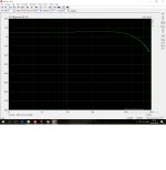
A few measurements.
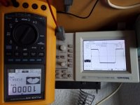
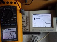
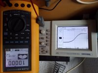
sound card is not able to deliver full voltage swing.
1. response
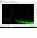
2. 1khz 20v rms
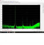
3. 10khz 20v rms.
sorry for the rotated pics.
i found an old noisy signal generator and with 1 khz amp started clipping at 45 volt or approx 250 watt into 8 ohm load. i dont have a 4 ohm load yet.
sound card is not able to deliver full voltage swing.
1. response
2. 1khz 20v rms
3. 10khz 20v rms.
sorry for the rotated pics.
i found an old noisy signal generator and with 1 khz amp started clipping at 45 volt or approx 250 watt into 8 ohm load. i dont have a 4 ohm load yet.
Attachments
Last edited:
Interesting, quite decent results. Thanks for posting. Bryston themselves quote distortion figures of < 0.005% 20Hz to 20kHz at 300 watts into 8R. However they do closely match all of their transistors, an option that isn't open to us.
In general terms I wonder how much of the distortion comes from the front end and how much from the output stage. The front end has lowish open loop gain and so there won't be an awful lot of negative feedback to lower the overall distortion. But maybe this is intentionally a low feedback design. Ideally Q5 and Q6 would be Darlington pairs and Q1-Q4 should have emitter degeneration. This would certainly give a degree of distortion reduction. The emitters of the vas transistors are heavily degenerated with R15 and R17 at 2.2k, and the vas current is a bit on the low side at only 2mA. Decreasing R15,R17 to, say, 470R would increase both the vas current and the open loop gain; I wonder how much effect this would have on the overall distortion? Good photographs by the way but I have to stand on my head to look at them, lol.
In general terms I wonder how much of the distortion comes from the front end and how much from the output stage. The front end has lowish open loop gain and so there won't be an awful lot of negative feedback to lower the overall distortion. But maybe this is intentionally a low feedback design. Ideally Q5 and Q6 would be Darlington pairs and Q1-Q4 should have emitter degeneration. This would certainly give a degree of distortion reduction. The emitters of the vas transistors are heavily degenerated with R15 and R17 at 2.2k, and the vas current is a bit on the low side at only 2mA. Decreasing R15,R17 to, say, 470R would increase both the vas current and the open loop gain; I wonder how much effect this would have on the overall distortion? Good photographs by the way but I have to stand on my head to look at them, lol.
Yes it doesn't quite live up to bryston nice specs, I will measure sound card it self, to see it's own distortion, then only the input stage, that must give an idea where to poke around.Interesting, quite decent results. Thanks for posting. Bryston themselves quote distortion figures of < 0.005% 20Hz to 20kHz at 300 watts into 8R. However they do closely match all of their transistors, an option that isn't open to us.
In general terms I wonder how much of the distortion comes from the front end and how much from the output stage. The front end has lowish open loop gain and so there won't be an awful lot of negative feedback to lower the overall distortion. But maybe this is intentionally a low feedback design. Ideally Q5 and Q6 would be Darlington pairs and Q1-Q4 should have emitter degeneration. This would certainly give a degree of distortion reduction. The emitters of the vas transistors are heavily degenerated with R15 and R17 at 2.2k, and the vas current is a bit on the low side at only 2mA. Decreasing R15,R17 to, say, 470R would increase both the vas current and the open loop gain; I wonder how much effect this would have on the overall distortion? Good photographs by the way but I have to stand on my head to look at them, lol.
But I will have to build a low noise buffer for my soundcard it cannot drive the amp, am looking at lme49600 capable of an quarter amp drive and 0.00003% distortion.
The harmonics on the spectra look a bit like crossover distortion "like soldiers marching off into the distance". Perhaps try to minimize distortion by carefully adjusting the quiescent current whilst observing the spectrum. Then try leaving it for an hour or so to see what happens to the distortion. I assume that the amp was driving an 8R load when you measured the spectra?
seller
Bryston 4B-SST High End Power Amplifier PCB Board Stereo Amp Module 120W-200W *2 | eBay
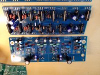
The ebay seller from whom amplidude got the PCB.This looks like a fun project, anyone tried this clone from eBay, it looks like first class pcbs
Bryston 4B-SST High End Power Amplifier PCB Board Stereo Amp Module 120W-200W *2 | eBay
thanks, chalky for your well detailed progress report, i bought the same boards and am buying components little by little. will keep following up on this thread 😉
Where can all the parts be bought from in the USA . Or has anyone made a group buy of the parts needed for these?
Great work guys on these and I’m thinking of buying these buy only after the smart guys work out all the bugs. Lol
Yes, I the not so smart guy but can follow step by step instructions. Lol
Almost all of the parts can be got from the usual distributors ( Mouser, Digikey, Farnell, RS ). I only had trouble with the pcb mount phono sockets and the input board heatsinks which I got from China via Ebay. We haven't come across any bugs as such - build it as it comes and it'll work - I've made a few small modifications and parts substitutions but these aren't necessary.
Like chalky said, they work if you follow the guidelines, and parts are pretty standard stuff.Almost all of the parts can be got from the usual distributors ( Mouser, Digikey, Farnell, RS ). I only had trouble with the pcb mount phono sockets and the input board heatsinks which I got from China via Ebay. We haven't come across any bugs as such - build it as it comes and it'll work - I've made a few small modifications and parts substitutions but these aren't necessary.
I noticed the voltage regulators on input board get rather hot, even with the small heatsink, think the transistors are close to their soa boarder, better heatsinkinking if you run high voltages, ohh and I blew the ntc resistors on the psu board, maybe cause the large toroidals and amount of mf, i will remove them and replace them with a large 23 ohm power resistor, and lastly, I am started on the bryston 28bsst yesterday, and the documentation is very poor, be advised.
Yes I only have an 8 ohm load, it's made up from 275 2k2 5 watt resistors, it can take some beating, I Will try adjusting bias with analyzer hooked up and see if I can get the soldiers back in their trenches🙂The harmonics on the spectra look a bit like crossover distortion "like soldiers marching off into the distance". Perhaps try to minimize distortion by carefully adjusting the quiescent current whilst observing the spectrum. Then try leaving it for an hour or so to see what happens to the distortion. I assume that the amp was driving an 8R load when you measured the spectra?
The 28bsst boards are interesting because they have the discrete component opamps, I assume for the input and output stage drivers, on a separate pc board. Makes it easy to experiment with different discrete opamps. I mention this because I'm in the middle of ( as with so many things ) designing a complementary differential, discrete component opamp with a couple of novel ( as far as I can tell ) features. Nearly finished building a perfboard prototype. If it works ok I'll post the details here.
Sounds interesting chalky, yes post it when ready, the output board is easily interfaced, it also contains a set of regulators to run input board, the +/÷ 33v, so it's all there like on 4b.The 28bsst boards are interesting because they have the discrete component opamps, I assume for the input and output stage drivers, on a separate pc board. Makes it easy to experiment with different discrete opamps. I mention this because I'm in the middle of ( as with so many things ) designing a complementary differential, discrete component opamp with a couple of novel ( as far as I can tell ) features. Nearly finished building a perfboard prototype. If it works ok I'll post the details here.
Is it the Douglas self inspired boards you were talking about a while ago?
No its like the Bryston discrete opamp but the input transistors have emitter degeneration and constant current loads. Common problem with this bare topology is that the vas current is undefined, so there are various stratagems to fix it ( Cordell, Stochino, Kleinschmidt, etc. ). I've come up with an alternative which is very simple and uses few extra parts - if it works.
I'm amazed at how quickly you build stuff - looking good! I ordered some of the 0.2R Russian military grade resistors you used in your 4Bsst build and also some of the 0.3R resistors that you have discovered too. Did you ever try adjusting the quiescent current of the 4Bsst to see what effect it had on the distortion spectrum?
Well, kids are grown up, so lots of sparetime, and I didn't buy components, I had them already at hand.I'm amazed at how quickly you build stuff - looking good! I ordered some of the 0.2R Russian military grade resistors you used in your 4Bsst build and also some of the 0.3R resistors that you have discovered too. Did you ever try adjusting the quiescent current of the 4Bsst to see what effect it had on the distortion spectrum?
No I didn't fiddle with quiescent current yet, just fixed the burned ntc soft start, and its now playing Jimi hendrix while pairing pn100a/200a.
Good you found the russian resistors, they are really nice, and precise, hardly any
Inductance
Hi
Any idea which output transistors are used in the Bryston 7B SST monoblocks?
I need to repair mine
Any idea which output transistors are used in the Bryston 7B SST monoblocks?
I need to repair mine
This should come in handy..Hi
Any idea which output transistors are used in the Bryston 7B SST monoblocks?
I need to repair mine
Attachments
- Home
- Amplifiers
- Solid State
- Bryston 4B SST clone