I've never seen that amp model, must be an old one. I'd be curious to see the whole schematic, and compare with what they're doing now, or at least their previous versions, since so far they're not sharing their newest stuff. I have yet to see any schematic for any cubed amps...
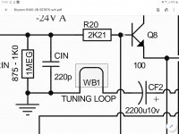
But this is interesting and it would be nice to know what's behind that thing. I'm guessing it would be some air core coil, somewhat similar to what's used on the output, but what's the real purpose and what does it do?
The circuit works fine without it, so I'm wondering what this extra thing brings to it.
Looks like you're right. I looked at other schematics and found the 2.5B model has that as well, explicitly mentioned a a tuning loop. I had never noticed this before, and never looked at the smaller 2.5B model, or I would've noticed.
So this is something to know more about.
So this is something to know more about.
Made a prototype for an "improved" DOA68 and tried a few things. First I tried simply adding degeneration resistors and the current mirrors with no attention paid to vas current prediction or stability. Amazingly the amp stabilised with a vas current of 15mA - a bit high but not too far from a sensible value. Probably helped that the transistors I was using were npn/npn, pnp/pnp, npn/pnp, matched out of the box. However it was just luck and the next build could equally well have had a vas current of 100uA or 100mA! After a bit of fiddling about I finally settled on a variant of the Sansui and Stochino methods for setting the vas current. Points in favour are that the vas current can be set simply and precisely, the vas current isn't sensitive to the betas of the input diff pair transistors, and the current mirrors don't need to be slugged with differential load resistors for the input diff pairs ( 10k in spookydds simulations ). Lack of the differential load resistors leads to higher olg and therefore less distortion. Prototype is very fast and very stable. Will post pictures tomorrow. I'm well pleased with it.

I can't wait. Please also post the schematic, so we can compare.
I'd like to try out your mods in sim as well.
Very interesting stuff.
If I can dispense with that diff res and the mods on the vas don't bring in much thd instead, we might have something worth using.
I'm still wrestling with my attempt at simulating the power amp with its doa ahead of it, which refuses to work without oscillating when they're both in the same sim. They do work great independently in separate sims...
Ok here are the photos, complete with a bit of hand shake blurring. They are respectively the prototype, a 1kHz sine wave, a 1kHz square wave, and a 10kHz square wave. As you can see the square waves are nice and clean with no sign of ringing. All voltages and currents as predicted and no oscillation. Result! I'll post the schematic when I'm a bit closer to something I want to commit to a pcb, in particular I really want to give the stability checking a hammering and fix it so that the circuit clips nice and softly.
Attachments

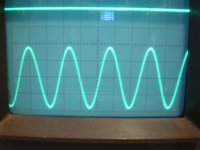

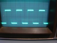
Just noticed that you can barely see the rising and falling edges of the square wave at 1kHz but they're clearly visible at 10kHz. Possibly a tiny bit of rounding at the bottom of the 10kHz falling edges too.
You're on the right path, looking good...Just noticed that you can barely see the rising and falling edges of the square wave at 1kHz but they're clearly visible at 10kHz. Possibly a tiny bit of rounding at the bottom of the 10kHz falling edges too.
I finally made that simulation work for the 28b full bridge.
It really is what I mentioned earlier, which is the issue isn't with the circuit design itself, but rather the simulator not being able to deal with that simulation very well.
It took a lot of attempts, many tricks to narrow it down. But basically it's not a matter of oscillations from the circuit, but rather the simulation not being able to find convergence, so the sim runs and runs basically forever, never finding a operating point, plus it complains about floating nodes as well, such as the input signal voltage source, because it's balanced, not directly referred to ground and it leads into capacitors only, with no resistors leading directly to ground. So it regards it as floating.
That floating node issue I just fixed with 2 large value resistors to ground, and at least shut it up about that issue. But it still has trouble finding the op point anyway.
After having tried tweaking some simulation parameters, like gmin, abstol, etc... I finally tried other simulation methods, plus I made it save the biasing into a file, so when it finally manage to figure out its op point, it gets saved and when reloaded the next time, that speeds things up by a huge amount, making run like a normal sim again.
The way to get bias info saved when it completes its convergence, is to use a less "picky" method, which is less accurate and helps it find its op point. But once the bias data is saved, an other method can then be used again, since it's loading the data instead of trying to find it again.
So now it works great, full bridge, 28b, even with the sub-circuit organization to make it easier to manage.
Results look very nice, stable amp, no oscillations. So now I think I'll start looking at a layout for a module...
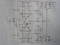
Mmm I'd be a bit wary of the lack of convergence. I spent my working like running simulations - molecules not electronics - and very slow or lack of convergence usually indicated that something was not as it seemed. Anyway made some some progress in checking out my prototype and along the way noticed that the output offset is exactly 0.00mV! Never had that happen before - 'course its brilliant design rather than pure chance. As its a long road from proof of concept to finished design I decided to publish my prototype schematic - warts and all. It seems to be very robust so I'll be interested to see what the simulation says.
Attachments
Hello again.
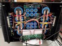
I had removed input board from the 4bsst to try other options, today I put it in place again, powered up and am now getting a really annoying 50hz hum, I tried isolate input board from chassis, no change, both RCA out, it's dead quiet, only left or right it plays as it should, so I must have a ground loop in input, I have dual transformers and have joined their ground, taking both grounds up to external sound cards RCA connector reduces the noise, but not totally, what have I done wrong, I'm sure the answer is simple, but to confused to think straight.
I had removed input board from the 4bsst to try other options, today I put it in place again, powered up and am now getting a really annoying 50hz hum, I tried isolate input board from chassis, no change, both RCA out, it's dead quiet, only left or right it plays as it should, so I must have a ground loop in input, I have dual transformers and have joined their ground, taking both grounds up to external sound cards RCA connector reduces the noise, but not totally, what have I done wrong, I'm sure the answer is simple, but to confused to think straight.
Is this with that clone or a real bryston amp?
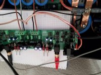
Could you post photos of that board? I'm wondering what they put on it. Where is the ground isolator in regard to that board? Photos would be nice..
Could you post photos of that board? I'm wondering what they put on it. Where is the ground isolator in regard to that board? Photos would be nice..
It's a working process, so it's a mess right now, but I succeeded in finding the ground loop, the culprit was the connector between the two ground busbars, flux ressidues made a bad connectionIs this with that clone or a real bryston amp?
Could you post photos of that board? I'm wondering what they put on it. Where is the ground isolator in regard to that board? Photos would be nice..
Attachments
Looks tempting.Mmm I'd be a bit wary of the lack of convergence. I spent my working like running simulations - molecules not electronics - and very slow or lack of convergence usually indicated that something was not as it seemed. Anyway made some some progress in checking out my prototype and along the way noticed that the output offset is exactly 0.00mV! Never had that happen before - 'course its brilliant design rather than pure chance. As its a long road from proof of concept to finished design I decided to publish my prototype schematic - warts and all. It seems to be very robust so I'll be interested to see what the simulation says.
It's a working process, so it's a mess right now, but I succeeded in finding the ground loop, the culprit was the connector between the two ground busbars, flux ressidues made a bad connection
So that's the clone, not the genuine bryston then.
Did you include ground isolators? DC blocker for the mains?
Where is(are) the transformer(s)?
Mmm I'd be a bit wary of the lack of convergence. I spent my working like running simulations - molecules not electronics - and very slow or lack of convergence usually indicated that something was not as it seemed. Anyway made some some progress in checking out my prototype and along the way noticed that the output offset is exactly 0.00mV! Never had that happen before - 'course its brilliant design rather than pure chance. As its a long road from proof of concept to finished design I decided to publish my prototype schematic - warts and all. It seems to be very robust so I'll be interested to see what the simulation says.
Have you done simulations yet?
As my previous attempts, this one also doesn't have something to forcibly define the vas bias, as many designs out there. It usually works in simulations. But lately we've been doing something to remedy that issue with the vas bias...
There's no DC blocker in it, ac here is stabil and clean, the two toroids are hiding under speaker protection 2.4kw in totalSo that's the clone, not the genuine bryston then.
Did you include ground isolators? DC blocker for the mains?
Where is(are) the transformer(s)?
Spookydd I don't understand what you mean. In my circuit both vas transistors are parts of current mirrors and the vas current is set to a rock solid 10mA by the 2.7k resistor feeding the other sides of the current mirrors. Side benefit is that the vas is current limited.
Keep noticing things to improve. The balanced to single ended conversion at the input amp in both the Bryston and the clone is very simple and results in different input impedances on the + and - outputs, as well as poor common mode rejection. In practice I doubt that this effects the distortion or the sound quality. But if we're nitpicking and talking about good engineering practiice - weeelll. I think I'll use a THAT1206 for this job on my input board design.
Spookydd I don't understand what you mean. In my circuit both vas transistors are parts of current mirrors and the vas current is set to a rock solid 10mA by the 2.7k resistor feeding the other sides of the current mirrors. Side benefit is that the vas is current limited.
That's just something we've been discussing lately, with current mirror fed vas, the vas base floats on the ltp, and we've been talking about adding a resistor across the ltp legs to force this, as prescribed by Cordell.
But I'm not familiar with that kind of topology as you described, and at the moment I don't know if it does solve that issue of undefined bias for the vas bases. Maybe it does, and perhaps you could elaborate on this, so the noobs (like me) can better understand how it works.
One thing I was wondering though, is why only 15V rails? With all discrete parts, there is no good reason not to go for much higher rails.
I see the fairly substantial tail currents and a fair amount of degen, should provide for some good slew rate...
Using those 2N5xxx may not be as low noise as with the BC5xx types though.
- Home
- Amplifiers
- Solid State
- Bryston 4B SST clone