What I mean is have a differential input buffer with a single ended output which drives the tied inputs two further amplifier modules, one with a gain of +1, and the other with a gain of -1. The latter two amplifier modules have single ended inputs and outputs.
Yes, that's how many bridges do it.
It's not what bryston does. And it's actually quite symmetric this way with the balanced inputs going to both but in opposite direction.
There is no reason why this wouldn't work, and it does work great with the original DOA and hooked up just like it is in the 28B amp.
The problem is when using the improved DOA. That's a bummer.
Surely if you omit R2 and R8 you've simply got an inverting amplifier on each of the in+ and in- lines.
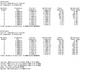
Here is a test of the improved DOA which is basically identical to that sub-circuit I made, especially since I used this rig as the base to put out the sub-circuit.
Works fine, on its own.
This improved DOA, has the "richer" tail currents from the ccs, for more slew rate... And rather hefty biasing in the vas and outputs, for a full class A regime, for nearly all of the output range, even under 600ohms load. It should hardly, if ever, get out of class A.
Works fine, on its own.
This improved DOA, has the "richer" tail currents from the ccs, for more slew rate... And rather hefty biasing in the vas and outputs, for a full class A regime, for nearly all of the output range, even under 600ohms load. It should hardly, if ever, get out of class A.
Attachments
Surely if you omit R2 and R8 you've simply got an inverting amplifier on each of the in+ and in- lines.
Sure, with no gain. And this does works (attached). But we need gain. The amps' gain is quite low and we need some in the front end to be able to drive those amps fully with a reasonable input signal strength.
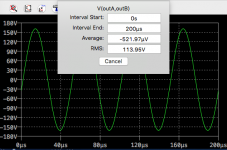
As you can see, it's fine that way, no oscillations whatsoever.
Attachments
What happens if you use 20k and 40k resistors a la Bryston?
Tried that, of course, with the bigger feedback cap 22p, in an attempt to curb that oscillation. But no change. The gain is the same anyway. I also tried with a bigger miller cap in the DOA, just in case, but no luck there either.
It's odd that it works quite fine with the original DOA, and it's wired just like bryston does it. I wonder what enhancements in the DOA could make this more prone to that issue.
By the way what is the frequency of oscillation? If its in the MHz can you simulate ferrite beads or rf chokes at the + and - inputs? Did you try it with just single transistors rather than cfps for the input differential pairs?
By the way what is the frequency of oscillation? If its in the MHz can you simulate ferrite beads or rf chokes at the + and - inputs? Did you try it with just single transistors rather than cfps for the input differential pairs?
I'm not sure how to simulate ferrite beads, but there might be something there to explore.
The oscillations are very high frequency, looks like well up there in the mhz.
I tried caps in some places to try to dampen this, if it could at least stop this until I can figure out why it's doing this.
Seems something is going on when the circuits are joined together, either at their inputs, or via their supplies, when they're common. I tried separating the supplies for the DOA, which seems to help some.
I also added input filters (R/C) and as long as the power amps aren't there behind the DOAs, this did stop them from oscillating. However they start oscillating again when the power amps are added behind.
I tried separating the supplies for the power amps as well. Just a short while ago, I had all of the supplies split from each other, so only a single supply for each circuit. It helps, to a degree, but not on the full config with everything hooked up.
The thing is, all this works just fine with the original circuits, where the only changes are how they're joined together, mostly removing all the gain switching shenanigans...
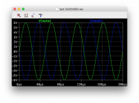
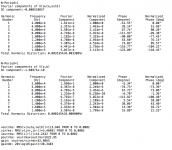
Screenshots attached, of the original bridge without any of the improvements, and only slightly altered in the interconnections.
This is at full power, slightly before onset of clipping, @20khz/8ohms. We get a little over 1.6kW with a 4.9V peak input drive signal, balanced.
I used the same gain setting resistors as the original, no input filters, and all the supplies are joined, and it works perfectly this way.
Attachments
Tried adding some explicit power supply decoupling for each module - elco + film cap?
Tried to some extent, without success, both using caps and in the parasitics in the supplies.
I'll try a more thorough approach, by doing it on all supplies. I have separated all the supplies, there are 12 of them.
Be odd if it was the power supplies as Bryston use a common power +/-33V power supply for all of the DOA68s.
I don't think it's something in the design itself but rather something inherent to simulation.
Some weird interaction maybe, with the supplies, but I did try all the supplies as independent and with decoupling caps on every one of them, but no difference.
I looked again at the design based on the original (DOA68+amp) and with the supplies combined, as I have posted earlier in that test rig, and it all works quite fine.
Something is happening with the alterations done. The mystery remains for now.
Did you try reducing the value of R27 and R28 from 10k to say 4.7k and/or increasing the value of the input and current mirror degeneration resistors? This will knock off some olg and may contribute to stability.
Did you try reducing the value of R27 and R28 from 10k to say 4.7k and/or increasing the value of the input and current mirror degeneration resistors? This will knock off some olg and may contribute to stability.
I didn't try going lower than 10k for those resistors (R27/28), I started from 100k and went down from there, but didn't want to drop them too low. It does bring a bit of extra thd, so I wanted to keep that to a minimum, or there is no point in adding the improvement, if it doesn't bring anything.
I did try a wide range of degen, but too much was really adding a lot to the thd, so I made a compromise that seem to work and didn't bring down the enhancement too much.
The circuits on their own work perfectly. So it's only when trying to marry them to make a larger simulation that trouble rears its head.
Right now I'm thinking I'm more wrestling with the simulator itself, with its quirks, than the actual circuit design.
I resigned to try a full side only, not as a bridge, just the whole chain from one side, from the input filters to a load to ground, with the DOA and amp and what's needed to make them work, but only one side.
Bringing the contents of more than one sub-circuit together into a single schematic, forces a review of signal labels that no longer need to be there because they're no longer "pins", and I have to do this because I end up with name collisions.
Now I'm wondering if at some point the simulator itself was getting confused with label names that were the same and coming from inside separate subcircuits. That may have caused some issues. Not sure...
I'm trying this right now, only one side, no sub-circuits, all in a single schematic...
I'm more and more thinking the issue is much more about the simulator than the circuit design.
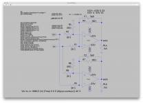
I made a test, bringing all the contents of the doa plus the amp in the same schematic, only for one channel, using the improved versions of the circuits, with just what is needed to make it work from the input filter to the output load, and the issue is there when everything is connected, but also when the doa is not connected to the amp part, even when they are totally separated by having separate supplies. So each circuit in its own schematic works great, with no signs of oscillation or anything else, but when in the same schematic, even if nothing electrically connects them, the issue is there.
I'll have to dissect this piece by piece to find out what's causing this "remote" interaction, causing oscillations, even when nothing connects the circuits together.
I also am looking at increasing the gain in the power amp section a little, because it's very low right now and the drive signal strength required is a little heavy.
Right now the power amp's global gain is at about x8, and if we set the doa's gain at x2, we're only at about x16 total gain, which requires close to 10V peak input signal to fully drive that thing. It's a bit much, so it requires a little tweak to reduce this requirement a little bit.
I already tried a higher gain in the circuit that I tested by copying the power amp's circuit into its own schematic, which works perfectly, even when I added hefty capacitive loading, no oscillations at all. I tweaked the amp's gain to almost x19 (~25db), adjusted the compensation a tiny bit, and loaded with extra capacitance in parallel with the resistive load. This pushed the amp to output even more power than the rails should allow, and there aren't any oscillations and the thd increases a bit but within reason, considering the torture...
I'll figure out how to get this to work somehow.
One thing I noticed that is interesting, is that because of the fully symmetric way of doing this, all the way from the input with both doa's being balanced and only in opposition, I think there is some cancellation effect to some aspect of distortion, perhaps only for one harmonic, which I suspect might just be the h2, so when bridged, the amp exhibits markedly lower thd than each channel independently (with same conditions for signal/freq/load/etc...)
So I think it's a good benefit to keep the architecture of fully balanced all the way, instead of trying to just use inverters and whatever...
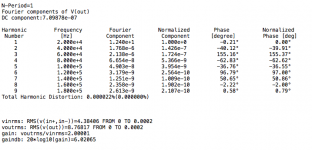
By the way, with the last tweaks done on the amp's gain with the slightly adjusted compensation, I get less than 20ppm thd before onset of clipping, on 4ohms resistive @20khz. No doa used in that simulation. The input signal required to do this, went down to 5.06V peak. This is pretty good, when we have a x2 gain doa ahead of it, this would be much more easily driven to fully power (~1.6kW before onset of clipping).
I made a test, bringing all the contents of the doa plus the amp in the same schematic, only for one channel, using the improved versions of the circuits, with just what is needed to make it work from the input filter to the output load, and the issue is there when everything is connected, but also when the doa is not connected to the amp part, even when they are totally separated by having separate supplies. So each circuit in its own schematic works great, with no signs of oscillation or anything else, but when in the same schematic, even if nothing electrically connects them, the issue is there.
I'll have to dissect this piece by piece to find out what's causing this "remote" interaction, causing oscillations, even when nothing connects the circuits together.
I also am looking at increasing the gain in the power amp section a little, because it's very low right now and the drive signal strength required is a little heavy.
Right now the power amp's global gain is at about x8, and if we set the doa's gain at x2, we're only at about x16 total gain, which requires close to 10V peak input signal to fully drive that thing. It's a bit much, so it requires a little tweak to reduce this requirement a little bit.
I already tried a higher gain in the circuit that I tested by copying the power amp's circuit into its own schematic, which works perfectly, even when I added hefty capacitive loading, no oscillations at all. I tweaked the amp's gain to almost x19 (~25db), adjusted the compensation a tiny bit, and loaded with extra capacitance in parallel with the resistive load. This pushed the amp to output even more power than the rails should allow, and there aren't any oscillations and the thd increases a bit but within reason, considering the torture...
I'll figure out how to get this to work somehow.
One thing I noticed that is interesting, is that because of the fully symmetric way of doing this, all the way from the input with both doa's being balanced and only in opposition, I think there is some cancellation effect to some aspect of distortion, perhaps only for one harmonic, which I suspect might just be the h2, so when bridged, the amp exhibits markedly lower thd than each channel independently (with same conditions for signal/freq/load/etc...)
So I think it's a good benefit to keep the architecture of fully balanced all the way, instead of trying to just use inverters and whatever...
By the way, with the last tweaks done on the amp's gain with the slightly adjusted compensation, I get less than 20ppm thd before onset of clipping, on 4ohms resistive @20khz. No doa used in that simulation. The input signal required to do this, went down to 5.06V peak. This is pretty good, when we have a x2 gain doa ahead of it, this would be much more easily driven to fully power (~1.6kW before onset of clipping).
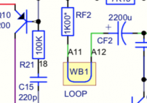
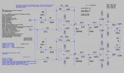
It looks like this in my schematic looping over traces?. Wire jumper..? English is not my best , what's it's name?Would anyone know what that WB1 loop is?
I never knew what that is and never seen this in any schematics anywhere.
I don't even know what that symbol means.
Attachments

Last edited:
It looks like this in my schematic looping over traces?. Wire jumper..? English is not my best , what's it's name?
No, that's definitely not something like this.
It's an actual symbol that means something, like some kind of loop/jumper, but not a simple jumper, it seems like something more. But what?
Think I have it,, it's a tuning coil,No, that's definitely not something like this.
It's an actual symbol that means something, like some kind of loop/jumper, but not a simple jumper, it seems like something more. But what?
- Home
- Amplifiers
- Solid State
- Bryston 4B SST clone