found some
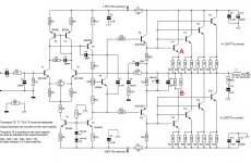
original sanken 2sc3284 ..... i am thinking on building the version shown above with 6 transitors per board and very rowbust 56+56 rails
any comments about the transitors ????
original sanken 2sc3284 ..... i am thinking on building the version shown above with 6 transitors per board and very rowbust 56+56 rails
any comments about the transitors ????
No comments about the transistors, Sakis, but it's sure been a long time since Quasi popped in here. Maybe him and Nordic are stranded on a desert island together.
Quasi, you here?? Let us know you're okay.
..Todd
Quasi, you here?? Let us know you're okay.
..Todd
for any interest
here is a list with some other npn i salvged from a company .... anybody has a suggestion please let me know ( or interest )
the list
2SC2578 NPN AF SWTC PWR 140V 7A 70MHz 10
2SC2921 NPN AF SWTC PWR 160V 15A 150W 25
2SC3182 NPN AF SWTC PWR 140V 10A 100W 419
2SD1049 NPN SWTC PWR 120V 25A 80W 10
2SD675 NPN AF SWTC PWR 160V 12A 100W 10
2SD752 NPN AF SWTC PWR 160V 15A 150W 11
BD245C NPN 100V 10A SOT-93 185
BDW83C NPN DARL 100V 10A SOT-93 565
BDW93C NPN DARL 100V 5A TO-220 50
MJ11015 NPN DARL 120V 20A TO-3 353
MJE340 NPN 300V .5A SOT-32 390
MJW2119 NPN POWER TRNS.250V 16A 200W 25
taj said:No comments about the transistors, Sakis, but it's sure been a long time since Quasi popped in here. Maybe him and Nordic are stranded on a desert island together.
Quasi, you here?? Let us know you're okay.
..Todd
On a desert idland with Nordic? aaaaarrrrrgh!!!!
Still around (alive) Taj, just crazy busy doing home improvement and keeping my day job. Being in sales during a GFC really sucks. I'll try and do some more diy audio soon.
Ciao friend
Q
ok doki ....
here is the question :
lets suppose that the circuit shown above like BOQ TO247 style is to be working with 3pairs of mjw 21194 and rails 63 volts (no load no signal)
my intention is to make this amp and power small stage monitors 10" or if results are nice may be power a 2way system for a low power application i have to run
what is the best way to protect this amp against abuse ..???? cause i think that if this amp is going to power either of the above application at some point it will be for shure abused
use of VI limmiters is a well known sonic killer ( does it worth to loose some of your sonics versus safety ???)
then again overdesign like use 5pairs of outs when you actually need only 3 ???? might be but no cost effective
underdesign the power supply so rails dive when the load is too much ????
use ideas like optocouplers driven from the balast resistors to compress the input signal ????
((( last night i was running a show that turned out to be a nightmare since i had a sytem calculated for 100 pax at the most and then more than 500 showed up . PA wise i had enough power to cover this but the stage monitoring was done with only 2 lines one numark amp that was the ST5500 thats about 250W @8R and double at 4R .... then monitors where 2*12" jbl and 2*10" AD...... which means that i was driving clip to the monitors all night !!!!! the amp was cliping constantly ....i wasnt actually afraid of the amp but mostly for the speakers ....well nothing happend speakers made it with no problems...WHY ????? was it soft clipping ????VI limmiters ???? or voltage dive from psu ????)))) and by the way ....at the end of the night you could just as well cook your breakfast on the covers of the numark !!!
thanks .... sakis
Hi,
fit a T rated mains fuse.
fit F rated supply rail fuses.
fit a DC detect circuit.
fit an input mute that is triggered by the DC detect.
fit an output relay that is triggered by the DC detect.
fit different release delays to both of those isolators.
fit IV limiting that allows all valid audio signals to pass to all valid load impedances.
The IV limiting can be two slope and should protect for the DC condition while the heatsinks are cold. The fuses are the medium and long term abuse protection.
The IV limiting must have a transient pass capability that allows at least twice the DC current to pass for medium term transients (possibly <=10ms) and at least three times the DC current for short term transients (possibly <=1ms).
fit voltage amp protection to limit when the output IV limits.
fit warning LEDs triggered by sink temp.
fit latched shutoff triggered by excessive sink temp.
IN THE THREAD
AMPLIFIER PROTECTION
this is the conclusion of all the related people
---- in the lower rail area , in one of the transistors between collector and idle there is to be placed an aditional resistor pack ( 2x1R /2W ) to provide curent sensing for a classic VI limiter
---Please notice points A and B where the limiter is to be conected
--- Opinion , or option, or alternative way to do this is very welcome
thanks
Attachments
Protection
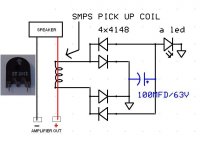
ABout 2 years ago I posted this. No reason it would not work with this amp.
http://www.diyaudio.com/forums/showthread.php?postid=1173157#post1173157
Cheers
Q
ABout 2 years ago I posted this. No reason it would not work with this amp.
http://www.diyaudio.com/forums/showthread.php?postid=1173157#post1173157
Cheers
Q
ok....
i produced boards and iam ready for testings ....there is going to be questions for sure
one of them
What about dumper resistor over the inductor coil ????
there is none in the schematic and none in any of the fotos i ve seen at least above
i produced boards and iam ready for testings ....there is going to be questions for sure
one of them
What about dumper resistor over the inductor coil ????
there is none in the schematic and none in any of the fotos i ve seen at least above
by the way
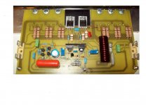
CAUTION MJE 340-350 HAVE WRONG MARKINGS ABOUT BCE ON BOARD CAUTION MJE 340-350 HAVE WRONG MARKINGS ABOUT BCE ON BOARDIdefixes said:I made some little evolutions on TO264 board to reduce the pcb size a little bit
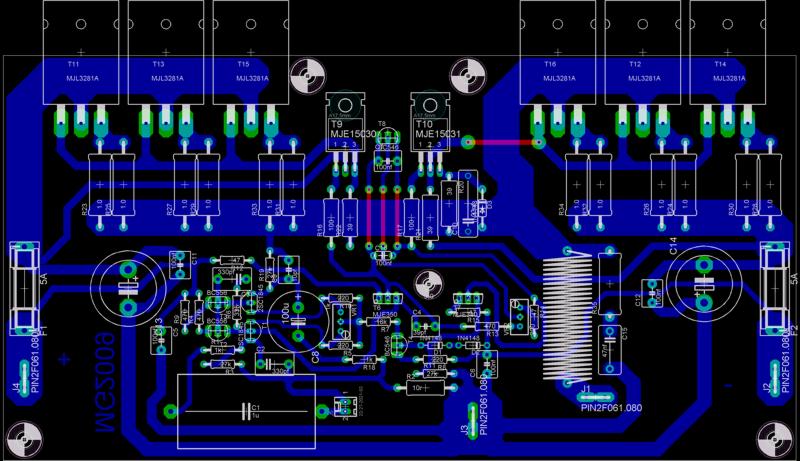
In the same time i manage to root a lighter version with 2 bipolar pair. It's for HT use or for more sensitiv seaker.

On Nmos tread quasi give some tips to estimate the number of necessary transistor pair based on power there power dissipation rating. I supose i can use this tip for bipolar. I will a highest use 35VAC trafo. The most power i could expect is about 190W/4ohm. With one MJL3281 and 360W power dissipation at 30% handle 360x0,3=108w with 2pair and 216w it seems to be good enough for my requierments. Am I right? In the same order Quasi shown on his web site a table with resitor value adaptation function rail voltage. Since mosfet and bipolar version of quasi have same topology at these location could the first one modification applied to the second one?
Marc
Re: by the way
Thanks for warning I will check this...
Regards Marc
sakis said:
CAUTION MJE 340-350 HAVE WRONG MARKINGS ABOUT BCE ON BOARD CAUTION MJE 340-350 HAVE WRONG MARKINGS ABOUT BCE ON BOARD
Thanks for warning I will check this...
Regards Marc
I just check with fairchild datasheet : orientation on my board seems to be OK with ECB from rigth to left (MJE340/350) since metal pad from transistor is looking to the top to be heatsinked.
Marc
Marc
YES
BUT THE MARK IS ON THE LEFT SIDE MEANING THTA BASE OF TRANSITOR IS TO BE PLACED THERE .....
if you re oriented by pins and not by heat sink you will make a mistake ...i did ...
BUT THE MARK IS ON THE LEFT SIDE MEANING THTA BASE OF TRANSITOR IS TO BE PLACED THERE .....
if you re oriented by pins and not by heat sink you will make a mistake ...i did ...
Re: YES
I am wrong in what i wrote over. You must read "ECB from left to right" If you looking to DS from fairchild it's the same orientation. Don't pay attention to the mark it's a eagle library i don't remember but i surely modify the pin assygnation without modifying the paking drawing by changing the mark position. Important is that pin assignation goes with schéma. If you compare my design this part is a copy of quasi work for TO3 model.
Marc
sakis said:BUT THE MARK IS ON THE LEFT SIDE MEANING THTA BASE OF TRANSITOR IS TO BE PLACED THERE .....
if you re oriented by pins and not by heat sink you will make a mistake ...i did ...
I am wrong in what i wrote over. You must read "ECB from left to right" If you looking to DS from fairchild it's the same orientation. Don't pay attention to the mark it's a eagle library i don't remember but i surely modify the pin assygnation without modifying the paking drawing by changing the mark position. Important is that pin assignation goes with schéma. If you compare my design this part is a copy of quasi work for TO3 model.
Marc
Re: Re: YES
any way have you tested any of these boards ????
Idefixes said:
I am wrong in what i wrote over. You must read "ECB from left to right" If you looking to DS from fairchild it's the same orientation. Don't pay attention to the mark it's a eagle library i don't remember but i surely modify the pin assygnation without modifying the paking drawing by changing the mark position. Important is that pin assignation goes with schéma. If you compare my design this part is a copy of quasi work for TO3 model.
Marc
any way have you tested any of these boards ????
Re: Re: Re: YES
Not a moment, i will have to recheck all befor etching them. I have in project to build 5chanel for HT. 2 of these in a box for front lateral. One of these and to with one paire of BJT for front center and rear suround.
Marc
sakis said:
any way have you tested any of these boards ????
Not a moment, i will have to recheck all befor etching them. I have in project to build 5chanel for HT. 2 of these in a box for front lateral. One of these and to with one paire of BJT for front center and rear suround.
Marc
Re: Re: Re: Re: YES
idefixes ...please e mail me privatelly .... please if you have the time check your pcb for any errors .... cause it seems that is not working
Idefixes said:
Not a moment, i will have to recheck all befor etching them. I have in project to build 5chanel for HT. 2 of these in a box for front lateral. One of these and to with one paire of BJT for front center and rear suround.
Marc
idefixes ...please e mail me privatelly .... please if you have the time check your pcb for any errors .... cause it seems that is not working
- Status
- Not open for further replies.
- Home
- Amplifiers
- Solid State
- Brother of Quasi