Sakis,
I don't understand what you mean. Output and driver (MJE15030/15031) are direct screwed on main heatsink. In my configuration amp PCB will be verticaly mounted so MJE340/350 could easy be cooled. The center screw allow to fix a small heatsink compare to a simple aluminium piece/U. The proxymity of each output BJT to other must not be a problem since the are direct screwed on main heatsink (I have 230x200x40mm heatsink with 10mm base), that must be enough for one chanel.
For insulator i will cut them in a sheet of Silpad 800 so no probleme. AndrewT said in a topic taht a classic TO3P is enough for TO264 package.
Marc
Idefixes said:AndrewT said in a topic that a classic TO3P is enough for TO264 package.
Most To247 are ~25mm x ~19mm.32mm x 23mm is enormous for a To247.
It will easily fit a To264. More than 2mm spare around every edge.
Your quote is so far off that it is completely misleading.
However, an earlier thread did say that with care a To247 could just be used for a To264. It would be up to the builder to decide if he/she were happy using the To247 insulator.
AndrewT said:
Most To247 are ~25mm x ~19mm.
Your quote is so far off that it is completely misleading.
However, an earlier thread did say that with care a To247 could just be used for a To264. It would be up to the builder to decide if he/she were happy using the To247 insulator.
Probably due to my poor english understanding. However i chose to cut my insulators to adequate size from a bigger insultor sheet. Andrew have you an opinion on layout and distance beetwen output BJT. Need I to grown PCB size to have bigger distance beetewn output BJT?
regards Marc
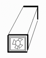
here is
another view under construction in old acoustica sassi with existing trafo end caps (fairly small though )
this is expected to deliver arround 180w per ch .... but trafo and caps will dive like hell much before full power
then the quesion is about cooling corner shapes are made with 5mm aloum . and attached back to back in this old 2N3055 heatsink and all of this is to be made a tunel with carton paper to ensure that 2 x12cm ventilators will drive the air directly through the heatsink ....
never done this before and i am really not sure if its going to be enough size of the hetasink is almost 20 cm long and the mechano is perfect like the corner shapes are fully attached on the heatsink very tight 6 x4 mm screws which is very flat and with loads of cream
An externally hosted image should be here but it was not working when we last tested it.
Lovely your board Sakis..... i love that massive heatsink to small transistors
The are exposed to air is much more important than how thick the aluminium block is....but looks great!
Yes...looks great.
It is good to see you building and producing pictures Sakis.
Is this one a Quasi amplifier?
Good!
regards,
Carlos
The are exposed to air is much more important than how thick the aluminium block is....but looks great!
Yes...looks great.
It is good to see you building and producing pictures Sakis.
Is this one a Quasi amplifier?
Good!
regards,
Carlos
I think your heatsink may work with 100 plus 100 watts RMS
and three times more if you decide to use paper tunnel and installing two fan blower, one pumping air and other exausting air.
But use a lot of thermal grease into this "L" shape adaptor, because there you gonna have a lot of thermal resistance.
Nice idea...pretty heatsink....good!
regards,
Carlos
and three times more if you decide to use paper tunnel and installing two fan blower, one pumping air and other exausting air.
But use a lot of thermal grease into this "L" shape adaptor, because there you gonna have a lot of thermal resistance.
Nice idea...pretty heatsink....good!
regards,
Carlos
Attachments
Use thermal compound Sakis
I am not sure, but i think the old style Mica insulators may be better than those modern ones...not sure...but using them here i felt them not very good...transistor case turns hotter than the heatsink...so, heat transference not very good, not very fast.
regards,
Carlos
I am not sure, but i think the old style Mica insulators may be better than those modern ones...not sure...but using them here i felt them not very good...transistor case turns hotter than the heatsink...so, heat transference not very good, not very fast.
regards,
Carlos
An externally hosted image should be here but it was not working when we last tested it.
this is
the way its done uncle charly ...only sides are wipped very clean ...there is loads of cream in between the corner shapes
the way its done uncle charly ...only sides are wipped very clean ...there is loads of cream in between the corner shapes
ok ...here is a question ...
i have a box that previously used to be an altair MF 16 Big mosfet amplifier> we asume that this amplifier has been hit by thunder cause there is no other explanation of the extnsive damage that the boards have .
caps are in perfect shape though Trafo also rectifiers are to be replaced anyway just in case i dlike very much to bulit a quasi inside there since the rest og the hardware exists BUT BUT BUT rails are almost 85+85 volt at no load condition
Do you think that a quasi with 10 outs will work under this rail voltage ????
may so many outs require base resistors also ????
here is a thread that i started with the intention to change/rewind the trafo and here is how it actually end up http://www.diyaudio.com/forums/showthread.php?s=&threadid=144445
quoted by os (ostriper )
Why not port the BO quasi to handle 85V? I use same OPS / input
with +- 80v all day !
Make all rail caps 100V , Change T2/3 to 2sa992(120v) and T4 to another 2sc1845(120v). use mje15032 / 33's for drivers(250v) , make r8 240- 270R.
A lot easier than rewinding the trafo. With 27K Rfb you will never clip , but be aware , at the higher rails you will be approaching SOA limits.
OS
quoted by megajoke
Agree. +-85V isn't that high. Actually, less than 10 pairs should be ok. How many will fit?
As a comparison, the Crest CA4 has +-90V rails and just 4 pairs of 2SC3281/2SA1302 in series-parallell (to get better SOA at high voltage). MJW21194 has better high-voltage SOA so series-parallell won't be necessary. Also, these are rated 200W instead of 150W like 2SC3281.
I am not following the Quasi amplifier threads
There's nothing i can say about Quasi....
i am not following that thread because
started with Fets...and this made i discard
the amplifier from my list of units to be
built... reason why i know nothing about and
cannot answer you...well..if this question was
directed to me...i am not sure about.
About transistors... each pair with 60 watts is
something reasonable...so..if your spectation is
300 watts..them 5 pair will be needed...this is
just and example..i do not even know the power
your amplifier will put out.
100 or 200 watts to each transistor is something
we obtain into datasheet (25 degrees)...real world
we stress those transistors when we make it to
dissipate more than 30 watts continuous... even
when using big heatsink.... stress in my mind is when
the transistor operates with temperatures higher than
52 degrées celsius measured into the heatsink,
and very near the transistor (not at the transistor top)
regards,
Carlos
Sorry sakis , I only guessed before with my BOQ advice. I was close. The only issue remaining would be increased VAS Iq (14ma+). The (attached) schema will show the changes. the higher Vce drivers- mje15032/3 and 2R2 base stoppers + 5 pair are
absolutely guaranteed. All currents and values are very close to lower voltage BOQ , so original performance should remain the same. 🙂
Edit - you might want to up r12 (15k) to 22k for 3mA across diodes... I use red LED at 20k = 4ma.
With 5 pair and the same feedback you would never ever clip and not exceed the power rating of the original BOQ but might have a
little more headroom.
OS
Attachments
oki doki
A BIT BACK IN THE VI LIMITERS TALK ......
there was this story that proper vi limiters cannot be placed in the BOQ since the topology of the amplifier features balast resistors in the lower rail side but emmiter wise so the criteria of a vi limiter if placed there will not be correct .
conclusion was that it has been established that most company that made quasi like peavey and qsc added one resistor in any of the lower transistors only for proper curent sensing .
here is an idea ....
i presume that VI limiter is symetrical but indepented ,one circuit per each rail side probably cause there is a chance that each rail might requier more or less limiting depenting on drive and load
why not current sense from the upper rail only and apply the limiting ammount via optotransitor to both rails ?????
Maybe because they gonna need protection to the optotransistor too.
And also protection to that protector..that finally will be another E/I limiter.
So...may be a dog cathing it's own tail.
regards,
Carlos
....................................................................................................
hehehehe
http://www.youtube.com/watch?v=3AWjzCRC174
And also protection to that protector..that finally will be another E/I limiter.
So...may be a dog cathing it's own tail.
regards,
Carlos
....................................................................................................
hehehehe
http://www.youtube.com/watch?v=3AWjzCRC174
Re: oki doki
Because it still won't activate if an overcurrent condition exists in the bottom half that doesn't also exist in the top half.
You can still build a load line limiter that works with a rail-connected as opposed to output-connected emitter resistor. It just looks different form the one on the + half. And I still fail to see why connecting one miserable resistor in the collector to do it 'normal' is such a big deal. If it didn't work as intended there wouldn't be as many CS800's still on the road as there are.
sakis said:why not current sense from the upper rail only and apply the limiting ammount via optotransitor to both rails ?????[
Because it still won't activate if an overcurrent condition exists in the bottom half that doesn't also exist in the top half.
You can still build a load line limiter that works with a rail-connected as opposed to output-connected emitter resistor. It just looks different form the one on the + half. And I still fail to see why connecting one miserable resistor in the collector to do it 'normal' is such a big deal. If it didn't work as intended there wouldn't be as many CS800's still on the road as there are.
hei wg ski
chil ...there is no need to run behind me .... if you closely look to any of the pcb i ve made you will notice that a big link is there placed ....and ready to be replace with a curent sensing resistor .
on the other hand do you find wrong that i like to look or invastigate other options ????
i allready have one prototype working made as above IE with an extra resistor and a proper VI limmiter working down under ....Made also various calculation to fit a limiter that meets the brother of quasi ...but still only practice will proof how well this is working ....
meanwhile i am looking to other alternatives , try to learn from it , explore digferent techniques ....if you dont mind
thank you my 250.000 watt friend !!!!!
another quasi
up and runing .... just finished today 60+60 volt rails 2sc3281 outs, 6 per board inside one old acoustica sassi featuring my weird heatsink located inside a tunel
tonight is going to serve monitors for a small dinner for a quitar vocalist ...
lets see
up and runing .... just finished today 60+60 volt rails 2sc3281 outs, 6 per board inside one old acoustica sassi featuring my weird heatsink located inside a tunel
tonight is going to serve monitors for a small dinner for a quitar vocalist ...
lets see
the particular
quasi found its way in a swiming pool event area yesterday .... there it supposed to drive 8 (!!!! ) speakers which with combination of serious parallel still present an 8 ohm load to the amplifier ....The task was casual background music but last night a party took place resulting many hours of DJ program music from CD players and often that amp was pushed to 100%
Some data
----created with 6 x 2sc3281 140V 10A 100W transistors (fairly small for the task ) per board .
----the amp produces about 180W with rails 60 volt biased at 100ma and with unmeasurable ofset ( total zero )
-----BUT !!! the trafo is totally 400w and the caps are 10.000x2 for the all amplifier
distortion when music approached 100% was more than obvious since rails probably dive very low on this load but at the end of the night amp was just a bit warm and all went just fine...it seems that my ventilation tunel worked just fine ....
so everybody is very happy and Quasi circuits start to prove very reliable ...
more tests , more boards and more versions coming soon
thanks leventi !!!!
Congratulations to you and to Quasi
This was a real test..and the amplifier was aproved.
So,...quasi amplifier and your construction are reliable.
Good!....i am happy to hear that.
Serious testing...real world use... full volume...near the clipping..many hours playing.... this is a good test..the real one.
Nice!
regards,
Carlos
This was a real test..and the amplifier was aproved.
So,...quasi amplifier and your construction are reliable.
Good!....i am happy to hear that.
Serious testing...real world use... full volume...near the clipping..many hours playing.... this is a good test..the real one.
Nice!
regards,
Carlos
By DX - This was a real test..and the amplifier was aproved.
Yes , this is the REAL test , how many parties

 can the DIY amp survive. The simulator can not party with the amp.
OS
will see
for me that was only a start
there has to be plenty more ....various loads....various musice ....various music.... various abuse
for me that was only a start
there has to be plenty more ....various loads....various musice ....various music.... various abuse
- Status
- Not open for further replies.
- Home
- Amplifiers
- Solid State
- Brother of Quasi