hmmmm
i would chmange the thicknes of the trace that supply the drivers etc. since the board now changes length wise ...
it seems to me that the trace is kinda small ...
in my boards i made them bit thicker but also feed them with aditional soldering for the all length
regards sakis
i would chmange the thicknes of the trace that supply the drivers etc. since the board now changes length wise ...
it seems to me that the trace is kinda small ...
in my boards i made them bit thicker but also feed them with aditional soldering for the all length
regards sakis
Re: hmmmm
Good advise I will modify this point , and lay on some solder.
Marc
sakis said:i would chmange the thicknes of the trace that supply the drivers etc. since the board now changes length wise ...
it seems to me that the trace is kinda small ...
in my boards i made them bit thicker but also feed them with aditional soldering for the all length
regards sakis
Good advise I will modify this point , and lay on some solder.
Marc
hi sakis
where are the protection circuits ie clipping,overload,short circuit protection you were talking of or running the amp without all these stuff.and where are the pdf's of this pcb.
thanks
ravs
be a vegeterian.
where are the protection circuits ie clipping,overload,short circuit protection you were talking of or running the amp without all these stuff.and where are the pdf's of this pcb.
thanks
ravs
be a vegeterian.
ravslanka said:hi sakis
where are the protection circuits ie clipping,overload,short circuit protection you were talking of or running the amp without all these stuff.and where are the pdf's of this pcb.
thanks
ravs
be a vegeterian.
The short circuit protection is outboard but wil be implanted. For the other as it's for a home huse (no PA application) for me, i don't need, the amp will be sufficiently dimensionned to not need to push it on extrem specifications.
Marc
so far
i have 3 quasis made to run all in small PA applications
one of them makes stage monitor inside a small club ( 280w out 6pairs per board, stereoversion, 1500va trafo 80.000 mfd total , 2x 12 cm fans )
other one 180w but only 21.000 mfd total for both boards and one trafo of about 500va ( permanenrt instalation swiming pool are backround music and it is expected never to be pushed or abused )
and the other one as the first ,250w per ch with 6outs and seperated heatsink for each board (45CM) and 4 x 8x8 cm vents serving parties and so on as generall pa use amplifier
the first one has a classic vi limiter only to sense from lower rail also features one resistor o.5R 5W to the collector of any of the transistors of the lower rail
the second one features no protection at all (taken as afact that psu will dive much lower than supposed to and act as protection
( the performance of the particular amp at full load of course is worst than terrible but it is never expected to be pushed or abused in tha particular application )
the third one uses a thermal and dc protection and a VI limiter with optocouplers that uses only creteria from the plus rail but apply the protection in both rails and a third opto that apply limit to the input through an ldr but then this is calculated to act if input exceeds 1.5 v
all these have been working for more than a month , daily ,and often pushed arround ...especially the second one that was very cheapo made ( had to serve a pary that was pushed to cliping all night ...with terrible sound but managed after all )
now as about schematics and layouts af the limiters i ve made i dlike to wait before posting anything since i am vey happy with the quasi so far regarding power , sonics, dynamics , response BUT i dlike to push them arround some time more before posting something that is not correct ...
so far so good
ravslanka said:hi sakis
where are the protection circuits ie clipping,overload,short circuit protection you were talking of or running the amp without all these stuff.and where are the pdf's of this pcb.
thanks
ravs
be a vegeterian.
i have 3 quasis made to run all in small PA applications
one of them makes stage monitor inside a small club ( 280w out 6pairs per board, stereoversion, 1500va trafo 80.000 mfd total , 2x 12 cm fans )
other one 180w but only 21.000 mfd total for both boards and one trafo of about 500va ( permanenrt instalation swiming pool are backround music and it is expected never to be pushed or abused )
and the other one as the first ,250w per ch with 6outs and seperated heatsink for each board (45CM) and 4 x 8x8 cm vents serving parties and so on as generall pa use amplifier
the first one has a classic vi limiter only to sense from lower rail also features one resistor o.5R 5W to the collector of any of the transistors of the lower rail
the second one features no protection at all (taken as afact that psu will dive much lower than supposed to and act as protection
( the performance of the particular amp at full load of course is worst than terrible but it is never expected to be pushed or abused in tha particular application )
the third one uses a thermal and dc protection and a VI limiter with optocouplers that uses only creteria from the plus rail but apply the protection in both rails and a third opto that apply limit to the input through an ldr but then this is calculated to act if input exceeds 1.5 v
all these have been working for more than a month , daily ,and often pushed arround ...especially the second one that was very cheapo made ( had to serve a pary that was pushed to cliping all night ...with terrible sound but managed after all )
now as about schematics and layouts af the limiters i ve made i dlike to wait before posting anything since i am vey happy with the quasi so far regarding power , sonics, dynamics , response BUT i dlike to push them arround some time more before posting something that is not correct ...
so far so good
So here the latest evolution with my design. I optimise the board size to fit to the heatsink i have in stock and to the pcb board i can by and manage. With a 300x200mm borad i can etch two amp board.
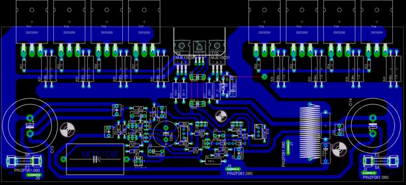
The heatsink mesure : 265x140x75mm with a 15mm base thickness.
Sakis : i grown the driver supply trace.
Marc
The heatsink mesure : 265x140x75mm with a 15mm base thickness.
Sakis : i grown the driver supply trace.
Marc
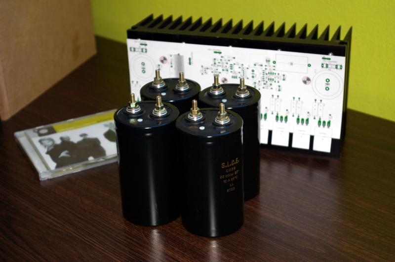
I will buid a first stereo version with parts i have in stock 'most of them came from industrial rubbish) : 4x 15.000µf/53V, 2x(330va 2X15V) I will put secondary in serie to have 2x(330Va 1x30v), heatsink above on picture, 16xMJL3281A from Onsemi. Then If i succeed i will build a second sterao amp in monoblocks form. I will then choose either 30vac or 35vac for supply depending how the first version will drive my speaker.
Marc
Marc
Hi Ide,
try to get your output devices bolted to the sink about 50 to 60mm up from the bottom edge to get best dissipation from your 140mm tall heatsink.
Your present PCB layout makes this impossible. You cannot turn the PCB to horizontal because the devices are not at the edge.
try to get your output devices bolted to the sink about 50 to 60mm up from the bottom edge to get best dissipation from your 140mm tall heatsink.
Your present PCB layout makes this impossible. You cannot turn the PCB to horizontal because the devices are not at the edge.
AndrewT said:Hi Ide,
try to get your output devices bolted to the sink about 50 to 60mm up from the bottom edge to get best dissipation from your 140mm tall heatsink.
Your present PCB layout makes this impossible. You cannot turn the PCB to horizontal because the devices are not at the edge.
Hi andrew,
The latestet version is 10mm small then this on heatsink on picture. With the new version if I placed the board on heatsink top there is 22mm beteew bottom edge and begin of output device I will look how i can manage to apply your advice. Brackett I have are 50x50mm (thickness 3mm) could allow this, but the first statement was to not use brackett

Marc
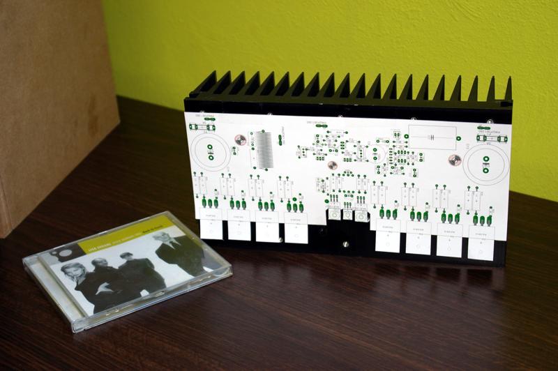
Nice board...
Idefixes,
I have to say your layout is wonderful, very neat, very artistic, and very good technically. You handle minor criticisms too with grace, I take my hat off to you,
Hugh
Idefixes,
I have to say your layout is wonderful, very neat, very artistic, and very good technically. You handle minor criticisms too with grace, I take my hat off to you,
Hugh
that's better than many can manage.Idefixes said:With the new version if I placed the board on heatsink top there is 22mm beteew bottom edge and begin of output device
The loss in heatsink performance will not be great, just be aware of it.
So i manage to change the output device position on board.
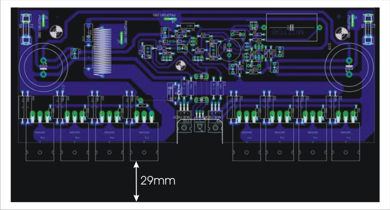
There is yet 29mm between heatsink bottom edge and output device begin.
Marc
There is yet 29mm between heatsink bottom edge and output device begin.
Marc
Re: Nice board...
Thanks for compliment. But I don't be the only actor on this work. I adapte to my own requierement quasi layout since i wanted to use TO3P devise and not TO3 once. My work was on this, on adapte pcb size to fit to my heatsink (i suppress DC protection that will be on a other board), alow the use of big polyprop. caps for signal input.
Marc
AKSA said:Idefixes,
I have to say your layout is wonderful, very neat, very artistic, and very good technically. You handle minor criticisms too with grace, I take my hat off to you,
Hugh
Thanks for compliment. But I don't be the only actor on this work. I adapte to my own requierement quasi layout since i wanted to use TO3P devise and not TO3 once. My work was on this, on adapte pcb size to fit to my heatsink (i suppress DC protection that will be on a other board), alow the use of big polyprop. caps for signal input.
Marc
latest info
it seems that the worst quasi i ve made has been seriously abused .
just to remind the particular quasi is made with 6 low power transistors per board / a total 400W transformer / 2x10.000mfd for the all amplifier
no vi limiters or any other form of protection and 2x12.5 cm ventilators in a tunel .....
so !!!! this amplifier was supposed to work in permanent installation swiming pool area and the duty was to drive 8 speakers 5.5"+tweeter as background music conected in serious and parallel presenting 8 ohms load to the amplifier plus long cable resistance .....
so far so good ...once people decided to havea party with this system driving everything on serious cliping .... everything worked realy ok no amps or speakers blown which i presume has something to do with the power supply that seriously dived under load ..... of course distortion level were very high ....
a couple of days ago ....a new party take place but in another area of the swiming pool amplifier an speakers were removed and reinstalled in another area .....of course the installer never thought that the speakers originally were conected in combination of serious and parallel ...... they used speakon cables from one speaker to the other ....meaning that each board had 4 SPEAKERS IN PARALLEL 8 OHMS EACH !!!!!! that is a load of 2 ohms per board plus long cables resistance ....
the demands on power were low since it was a dinner party no club style abuse ....and yet again
all worked just fine......amaizing dont you think ????
Hi sakis,
can you remember us the whole amp configuration (rail voltage, nature and quantity of output devices....)?
Marc
can you remember us the whole amp configuration (rail voltage, nature and quantity of output devices....)?
Marc
Re: here is
its this one 6 trs 2sc3182 40+40ac almost 56+56 dc 2x10.000mfd ( for the all amplifier ,2boards ) and trafo is bearly 400 w
sakis said:another view under construction in old acoustica sassi with existing trafo end caps (fairly small though )
this is expected to deliver arround 180w per ch .... but trafo and caps will dive like hell much before full power
http://www.eastelectronics.gr/image/boq-3.jpg[/IMG]
its this one 6 trs 2sc3182 40+40ac almost 56+56 dc 2x10.000mfd ( for the all amplifier ,2boards ) and trafo is bearly 400 w
is that two channels, each 180W into 8ohms from a 400VA, 40+40Vac transformer?
and +-10mF/channel or +-10mF for the whole amplifier?
and +-10mF/channel or +-10mF for the whole amplifier?
you need to see the all post
Andrew to understand
this particular amp was made in one existing box previoulsy known as acoustica producing 120+120w @8 ohms and almost double at 4
the rail voltage is 56+56 volts the bank is 2x10.000 mfd for the all amp ( 2boards ) and yes at resistive loads one chanel driven the power is bearly 180w
as i said before this was done in an existing housing and since this was low demand device i see no reason to change more things on it
- Status
- Not open for further replies.
- Home
- Amplifiers
- Solid State
- Brother of Quasi