Thanks quasi for these documented replies. What is the limit for you in output pair number need to drive a low impedance load such as one who will sink to 2-3ohm; for exemple a typical MTM made on 8 or 4 ohms driver, sensibility is here not a issue since it will be over 90db, than 60W 8hms and 100/120W 4ohms will be more than enough for my own use. I reapet that number output device is not a issue for me i have more than enough in stock.
Regards Marc
Regards Marc
For home domestic use with your DC rails I would go with the following guide.
8 ohms - 1 pair
4 ohms - 2 pair
2 ohms - 3 pair
Cheers
Q
8 ohms - 1 pair
4 ohms - 2 pair
2 ohms - 3 pair
Cheers
Q
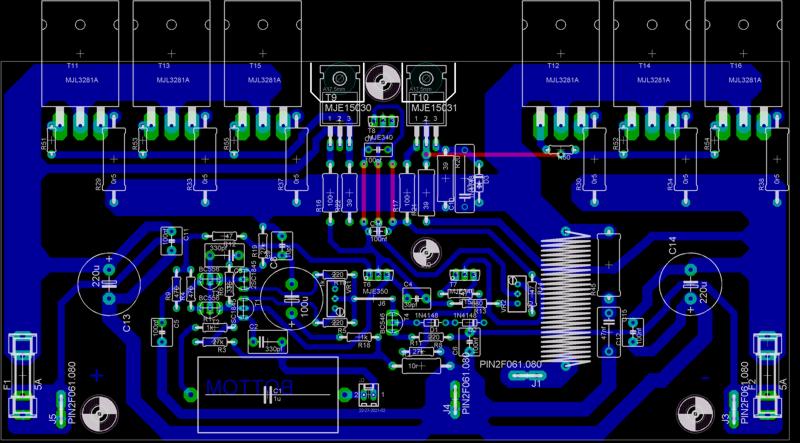
Thanks quasi for answers. I include this in the pcb drawing and manage the Nbip 3.35 TO264 version (3 for 3 output pair and 35 for 35vdc rail)
This is the version i will proceed. Next step is matching output devices, than i have to purchase 2SC1845 and match them...
As i explain below, ths PSU will consist into a 300va 2x25vac toroid and two 22.000µf/40V terminal mallory cans pro chanel. Soft start and DC speaker protection will be mount too.
Marc
oki doki here is some importand upgrade
the design and use of emmiter collector resistors of 1 ohm X2 2W each ...will present an equal of 0.5R 4W ....
Now if the tranistors A are real tranistors and can really force curent through this resistors these will FAIL !!! if amplifier is pushed to the edge it might be ok with casual listening
then the problem is that if only one resistor fail ( quiet common for lower quality resistors ) this problem will escalate one resistor will force the other both of them will force the transistor and then the all thing will get out of hand and amplifier will fail ...
so A ) may the value of 1 OHM is quiet big and needs to be recalculated to sotheing like 0R82 or even 0R68 while making sure that the resistors are the best regarding quality
or B ) new pcb is to be designed to accomodate classic 0R39 5W rowbust resistors....
(this actually happend to me while testing one version with only 2 sets of transitors and only 52 volt rails .....most my testing include also hard clipping in 4 ohm load ....under this amplifier will fail .... )
Sakis i think you could easyly mount 5W resistor (maybe verticaly) on actuel PCB as it is on Nmos200 pcb
What's wrong with using a pair of 1r0 2.2W resistors as an emitter resistor?oki doki here is some importand upgrade
the design and use of emitter collector resistors of 1 ohm X2 2W each ...will present an equal of 0.5R 4W ....[/I]
I reckon each 0r5 4W resistor can pass 5.6Apk to take it to it's 4W limit.
How long would this continuous high power last for? 1second, 2seconds, 5seconds.
1.4Vac across 0r5 dissipates ~4W. But each emitter resistor passes only half the wave form and as a result dissipates just half the power.
If we increase the voltage across the emitter resistor to 2Vac then the resistor dissipates 8W if continuously loaded, when on 50% duty cycle it will dissipate just 4W.
2Vac is equivalent to 2.8Vpk when on sinewave signal.
2.8Vpk across 0r5 is equivalent to 5.6Apk.
Output to the speaker is ~ 5.6A*5.6A*8ohm / 2 = 125W of continuous sinewave output power.
We all know that music is played on average at much lower levels than near maximum output power of the amplifier.
If the amplifier has 2pair then the emitter resistor will hit their dissipation limit when output is 250W into 8ohms and 3pair will go to 375W into 8ohms.
Sakis,
please tell us why a 5W resistor will work and a pair of 2.2W resistors will fail.
Last edited:
this what was the problem i faced during the test of one of these amplifiers ...yet again this might be related to the quality of the resistor .... i dont know where you find the 2.2 w as far as i know it is 2 w
during hard clipping at 4 ohms the resistor failed ...the temperature on it was above 65 degrees and the resitors failed ...
during hard clipping at 4 ohms the resistor failed ...the temperature on it was above 65 degrees and the resitors failed ...
the design and use of emmiter collector resistors of 1 ohm X2 2W each ...will present an equal of 0.5R 4W ....
Now if the tranistors A are real tranistors and can really force curent through this resistors these will FAIL !!!
or B ) new pcb is to be designed to accomodate classic 0R39 5W rowbust resistors....
Sakis,
please tell us why a 5W resistor will work and a pair of 2.2W resistors will fail.
Hello everyone!
I have a problem with my amp so if somebody could give me any advice I would be thankful!
The thing is:
My bias current is constantly dropping from he moment I turn on the amp. During this period I can even adjust it over small trim pot until it drop to like 10mA. Another thing is that the amp even plays music during that period and then shuts down.
Bias current was constant before I tried music on it...
Please help!!!
Thanks in advance,
Misha
post pictures of you construction it is obvious that you made some mistake .... it will be wise to know whta tyope of pcb you use .... that also means that we have to know what type of outputs do you use
if ypou use the original quasi pcb ore the other made by our friend for to247 devices it is very possible that yopu made some mistake while copy of the pcb
let us know ...kind regards sakis \
if ypou use the original quasi pcb ore the other made by our friend for to247 devices it is very possible that yopu made some mistake while copy of the pcb
let us know ...kind regards sakis \
It is a Quasi's PCB! I use mj21194 for outputs.... also I mentioned that amp did worked fine....
You can find my previous posts with pics here:
http://www.diyaudio.com/forums/solid-state/88258-brother-quasi-17.html#post1392785
You can find my previous posts with pics here:
http://www.diyaudio.com/forums/solid-state/88258-brother-quasi-17.html#post1392785
Last edited:
very well then ....is it the one chanel is it both chanels ??? is there a chance that any of your wiring with the VBE went faulty ....is there a chance that is something wrong with your trimmer ???
both channels are reacting the same way...
Same error!
Regards zeoN_Rider
If you have the same condition on both channels the I would examine the power supply. Have you lost a rail or ground somewhere? Do you have a soft start that may be faulty? The fault sounds pretty wierd especially for both channels.
Bad ground wire from power supply to the boards! Problem solved!
Thanks guys!!!
Nice work !
Cheers
Q
yeap i will go for that to .... it is nice work ....only negative i ve seen is that the aloum. corner that supports the outputs hasnt got the proper size ....
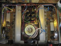
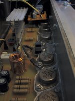
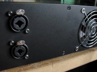
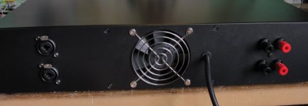
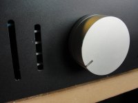
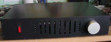
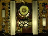
This is it!!!
After a long pause, Quasi-bip-amp is finally finished!!!
Sound is really nice and balanced from the lows to the crystal highs...
Thanks everyone for their support and specially Quasi for his hard work and help during the built!
After a long pause, Quasi-bip-amp is finally finished!!!
Sound is really nice and balanced from the lows to the crystal highs...
Thanks everyone for their support and specially Quasi for his hard work and help during the built!
Attachments
- Status
- Not open for further replies.
- Home
- Amplifiers
- Solid State
- Brother of Quasi