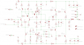
Don't care about Led3, C7. I don't mount them. Right value for R12, R15, R8 are schematic one i jointed here.
Marc
Aren't the 5A fuses in the wrong place, in the schematic?
Aren't the 5A fuses in the wrong place, in the schematic?
Take a look at quasi's original schematic.
Marc
Attachments
Take a look at quasi's original schematic.
Marc
Yes I do see that and there is nothing wrong with Quasi's schematic. Please observe where the rail power is given. If the fuse blows, the output section is disconnected from the supply but the input section will still be powered.
However, the way you have drawn the schematic, if the fuse blows, it is the input section which will be disconnected from the rails and the output sections will still be connected to the full supply. Ofcourse, the way it is drawn in your schematic, there is hardly a chance that the 5A fuses will ever blow.
I have not seen the way the track is laid out, so no comments on that.
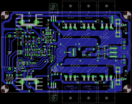
My schematic is the directe copy from quasi one. Mine is made under eagle. The the schematic is split into layout. Components connection are showned with unrouted line son complet correlation between schematic and routing job. If you take care to my layout above you can see that first stage is supply feeded before fuse son complete conforme to schematic and as quasi design it.
Marc
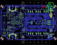
Add on : Take a look at add on drawing : red arrow for first stage power feeding and yellow arrow for output power feedings. You can see that output power supply must go through fuse tu supply output stage.
Attachments
Last edited:
Fuse placement rationale
The fuses are intended to provide a protection of last resort to the power suply, speakers* and output stage** in case of a catastrophic failure. The input and second stage are left unprotected for a couple of reasons.
1. The input and second stage need to be free from voltage fluctuations caused by the fuses during heavier power outputs.
2. There is no point trying to protect a circuit section that draws around 50mA with a 5 amp fuse. If there is a problem then this section is doomed regardless of the fuse you choose.
* Speakers should always connect via a DC detect circuit with a high current relay.
** If you blow a fuse that is correctly rated then the output stage is probably already dead.
Cheers
Q
Thanks for well argued explaination.
After running Nbip and TSSA BIGBT i have in mind to build some test plateform based on +/-35VDC (so common power supply, soft start, DC prtection, heatsink, casing and connectic) with easy amp board swatch ability. These will be mounted on L bracket that just screw on heatsink. So to swap from an amp board to another i just have to unconnect (rails, gnd, in and out signal), unscrew amp/L-bracket combo) and screw un another.
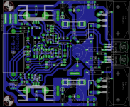
I plane to realize SSA, LME49810/TT, Baby Aksa, and Nbip 1, may be other going on moment inspiration. So for Nbip i build a new layout allowing L bracket mounting. The board size is 100x105mm wide. See attachement for schelatic and layout. Feel aware to give your feeling.
After running Nbip and TSSA BIGBT i have in mind to build some test plateform based on +/-35VDC (so common power supply, soft start, DC prtection, heatsink, casing and connectic) with easy amp board swatch ability. These will be mounted on L bracket that just screw on heatsink. So to swap from an amp board to another i just have to unconnect (rails, gnd, in and out signal), unscrew amp/L-bracket combo) and screw un another.
I plane to realize SSA, LME49810/TT, Baby Aksa, and Nbip 1, may be other going on moment inspiration. So for Nbip i build a new layout allowing L bracket mounting. The board size is 100x105mm wide. See attachement for schelatic and layout. Feel aware to give your feeling.
Attachments
Last edited:
- Status
- Not open for further replies.
- Home
- Amplifiers
- Solid State
- Brother of Quasi