Yes. It is a hard problem to analyze / simulate correctly. Not impossible, but hard. Someone who knows what they are doing with FEA needs to spend some time on a given design in order to arrive at a valid analysis.
I started to put together an article a year or so back using open source FEA only to find that viscoelastic damping models weren't implemented. It would have been possible to put something together without but when studying resonances getting the damping reasonably correct is required to get the amplitudes of the resonances reasonably correct. Instead I added implementing one to the to-do list but haven't got round to it yet.

3M VHB double sided tape is viscoeleastic material. Easily sourced and cheap.Also, Turbowatch2 makes the correct claim that any sandwich material needs to be viscous. Sorbothane is an obvious material but quite expensive. But finding information on the viscoelastic measures for neoprene, butyl rubber, etc, is difficult. I thought I had found at one time that neoprene was not viscous and butyl was, but I have not been able to confirm that.
The bolt with rubber washer is a good idea and makes sense to me. I don't think I'll need the rubber as the bolt will be secured to the brace but the brace will be elastic itself. I'm going to see if I can find an adhesive that will bond TPU and wood as I think that is the simplest, most elegant, solution.
😀Yes. It is a hard problem to analyze / simulate correctly. Not impossible, but hard. Someone who knows what they are doing with FEA needs to spend some time on a given design in order to arrive at a valid analysis.
I can confirm that.
The journey starts with the material properties. I spent a couple of days to try to model the MDF material properties. (Anisotropic) At the end the measured resonance frequency of each cabinet wall was surprisingly close to the simulated result.
For a typical mid the ratio cone weight/total weight is in the order of 2%. Since panel resonances appear at mid frequencies, you could skip the woofer and tweeter. I don’t really see the issue, apart from the assumption that in normal conditions modest panel resonances would be problematic, is debatable itself.but this reduces the mass the moving cones react against which tends to be fine for tweeters, debatable for mids and a problem for woofers.
I've used constrained layer to great effect. Loudspeaker panels shouldn't be monolithic layers of birch plywood, although that's a really good enclosure. I've found that two or three thin layers of very different materials glued strongly to each other make a less resonant panel than one solid 3/4" plywood or MDF panel. I've used 1/4" layers of HDF/Ply/veneer, one of my favorites is MDF/cement board/ birch plywood. The options are huge, you can use foam core, aluminum, lead, gypsum board, linoleum, etc. The different materials seem to diffract or refract the sound traveling through the panel. The three layers stacked seem to add stiffness. You can make panels that are lighter than plywood and panels that are heavier. It's great for experimenting and unfortunately, using lots and lots of glue. This is not the same damping technique used in an earlier post where neoprene, a soft material, is sandwiched between two layers of stiffer materials.
As far as bracing and damping go I've commented before that Dave's beautiful Jules Vern type speaker bracing actually acts as damping by eliminating any resonances in the box. Also, it's one ******* stiffly braced box.
As far as bracing and damping go I've commented before that Dave's beautiful Jules Vern type speaker bracing actually acts as damping by eliminating any resonances in the box. Also, it's one ******* stiffly braced box.
I've experimented with isolating the woofer frame from the front panel and found that supporting the woofer from the magnet with a stiff brace works best. The baffle stays isolated and a damping material gasket is between the woofer frame and the front panel. The woofer is supported by the brace that is mounted to the inside of the cabinet or to the floor. Another option is to mount two woofers back to back in a force canceling alignment. There isn't much if any improvement by placing a gasket between the woofer and front panel and then screwing or bolting them together. Also, the best results are of course with enclosures with large front baffles.
Look at the brace, it is not glued solid to the sides, but uses a flexible glue to 'eat' up vibrations. At least that's what they do in the LS50 Meta.
I am really wonder about that ?! The LS50 has a partially polymer cabinet instead of 100% wood ?
The brace is to re enforce stifness and avoid the baffles to inflat/exflat, so have micro vibrations if I understood the theory about that.
Imho the structure should be glued stiff or screwed mechanically with its braces. If not coupled from a side to an other, then a third cheet of wood could couple the two opposites braces with those flex glue in order just that sheet in the middle vibrates and so transform force in heat (contrained layer damper effect.(mass spring mass).
Eventually a thin metal sheet plan of no more than the mm in thickness can be gluesd with very thin flexible glue layer (less than the thickness of the metal sheet) on the flat surfaces still free in order the metal vibrate. Constrained layer damping effect again. It is harder to do than the bitumen pad but has advantages : it doesn't mass load the main cabinet.
Structural engineer like @gaszto will confirm or not if exact. The shearing effect wanted by flexible glue is going against the targett of stiffening the side panel with braces. But as all of that depends of the quantity of force involved, the trade off is not clear to me. Buut if only one brace is glued to a standalone side panel with flexing glue, it is not evident that only the brace will shake at dissipating heat. You have a chance the side pannel shake too if flexing glue is used everywhere and shaking = singing, and outside when it is the worse.
I believe bitumen pad is only usefull to avoid the internal back wave of the lowest wave-lengths, so in the highs to excite the pannels,but where it is counter productive is their weigth in a single 3 ways cabinet lowish the main resonance that are more harmfull.
Last edited:
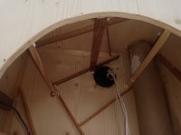
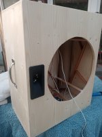
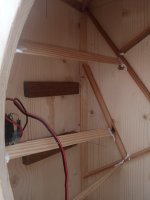
added now some braces back to front.
Here the knuckle test shows clearly a benefit raising the frequency of resonance

most important is the driver itself:
sandwich alu foil paper alu foil. Foil is 3x thicker than household foil.

Here the knuckle test shows clearly a benefit raising the frequency of resonance
most important is the driver itself:
sandwich alu foil paper alu foil. Foil is 3x thicker than household foil.
Attachments
A usefull information to know is where the most forces are comming from : the back wave of the driver or its structure ? Motly to know how dealing with the front baffle vis à vis of the drivers and the cabinet.
Last time I asked in this often discutted thread, the main culpritt was the frame of the driver much more than the back wave energy, but I really don't know.
Last time I asked in this often discutted thread, the main culpritt was the frame of the driver much more than the back wave energy, but I really don't know.
@diyiggy
its known that if you have a "weak" enclosure decoupling of the driver is of great benefit.
Sometimes I have problems to do this because using insulation tape is disturbed by the holes on the driver for fixing it.
A perfect polyurethan insulation would be ideal.
Sometimes I glue a driver in with silicone omitting fiddling with stripes of insulation like "Tesa Moll"
Last edited:
if decoupling should be done correctly the screws should be layered on silicone rings but I never was consequent enough to do this, so only half the job done.
I tried a thick foam sold in the drivers distributors, it is black and react strangly (badly) to the compression. I think stiff fixing is maybe better as is saying T Gravsen. But in the diy loudspeaker I made I wanted them to be removable... ahah you can't have it all at once at the same time in the multiverse of our hobby ! 🙂
@diyiggy
its also known if the driver is layered softly / decoupled from the box it gets an own resonance which can be measured. In a german diy magazine they gave the technical proof for it showing measurements.
Even a weak plastic or metal basket can show a resonance the driver bending itself.
its also known if the driver is layered softly / decoupled from the box it gets an own resonance which can be measured. In a german diy magazine they gave the technical proof for it showing measurements.
Even a weak plastic or metal basket can show a resonance the driver bending itself.
- Home
- Loudspeakers
- Multi-Way
- Bracing VS Damping