I agree completely.................
Having built this preamp with both versions of the volume control I can say that the one with the stepped attenuator is a clear winner as regards my needs..................
The standard version with the very high gain and the very unmatched left and right at low volume is operationally very inconvenient.
I too find the switched version much better to use.
I used a very cheap PCB based Chinese 33 position dual track switch.
I unsoldered all the as built resistors.
Soldered in standard 600mW 1% 50ppm/C metal film, close to the values in the table. (mostly from Rapid-online and a few from Farnell).
Added on the two extra "end" resistors.
Took a while, since precision soldering is required to get all the resistors standing on end and fitting inside the folded metal casing without fouling the side nor the wiper mechanism.
SMD 603 would have been a better solution but did not have the right values in 805 and no values in 603
805 could have been made to fit if I had staggered the ends, otherwise they would have been a little bit too long.
Last edited:
I made a mistake and put the regulators wrong way in my board.I was using a generic 7812/7912 regulators.
I tried later with the new regulators and now correct way.Unfortunately looks like the board is not working.
I am using a board from this gb.
http://www.diyaudio.com/forums/grou...tzeys-balanced-preamp-group-buy-part-2-a.html
Any ideas,what else components there could be broken after the regulators were first wrong way?
Did you check with the new regulators in place whether they were producing +/- 12 volt?I made a mistake and put the regulators wrong way in my board.I was using a generic 7812/7912 regulators.
I tried later with the new regulators and now correct way.Unfortunately looks like the board is not working.
I am using a board from this gb.
http://www.diyaudio.com/forums/grou...tzeys-balanced-preamp-group-buy-part-2-a.html
Any ideas,what else components there could be broken after the regulators were first wrong way?
There is not too much that can go wrong. The opamps can have +/- 18 volt,
But the input resistors in the power line may be burned and no longer conductiing, that's why you have to check the +/- 12 volt first
Hans
Has anyone shared a Front Panel Designer layout for this board? I read this and associated threads quickly but didn't find anything. I know it shouldn't be hard to do, but I can't figure out the center to center spacing until I get the boards in hand.
Thanks for any help.
Thanks for any help.
Finally in a position to finish my BPBP from the first group buy. The one thing I dislike is the drilling of the holes for the XLR connectors. Has anyone in the group created a drilling template by chance? Or other thoughts?
Thanks
David
Thanks
David
Slightly confused David, I thought the holes already in the PCB lined up with the Neutrik XLR part?
They do. I am talking about drilling holes for mounting the xlr to the chassis back panel. I may just have to learn how to use Front Panel Express software!!
David
David

It seems like I saw a posting for either a FPX layout or a HiFi2000 layout, just can not remember which or where. Aging is fun.
Jan Didden posted front panel designer files in one of the threads recently when I asked the same. Perhaps it was the latest group but thread if not a few pages back here.
There is also a DXF file in this documentation set
https://www.dropbox.com/sh/0rxpg5lfxvju9g0/AADqEbF6N7WFk777vFS9e35Ga?dl=0
Hans
https://www.dropbox.com/sh/0rxpg5lfxvju9g0/AADqEbF6N7WFk777vFS9e35Ga?dl=0
Hans
Hi Xavier,
It seems that my shipment is lost somewhere on the way from London to ???
I contacted a local mailing service and this was their (translated) response:
"Regarding your request, we want to inform you that the said consignment is not arrived in Croatia.
Therefore, please contact the sender, about the possibility of starting the inquiry process."
Therefore, I would be grateful if you could look at what happens to my parcel.
Attachments

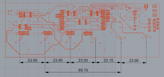
Could someone tell me the outside dimensions of the board? We're planning on a making a preamp chassis for the store with drilled holes in the back for any Neutrik connectors, and
a nice faceplate with holes drilled partially through from the back. Want it to fit most boards out there! Incidentally the mounting holes in the chassis for signal level boards (ie anything not attached to a chassis heatsink) is a 10x10mm grid, so if you're designing any boards use mounting holes spaced on as 10mm x 10mm grid..
a nice faceplate with holes drilled partially through from the back. Want it to fit most boards out there! Incidentally the mounting holes in the chassis for signal level boards (ie anything not attached to a chassis heatsink) is a 10x10mm grid, so if you're designing any boards use mounting holes spaced on as 10mm x 10mm grid..
- Home
- Source & Line
- Analog Line Level
- BPPBP - Bruno Putzey's Purist Balanced Preamp (well a balanced volume control really)