Bruno repeats what AES specifies, ty pin1 as soon as possible to the chassis ground.
That is exactly what the right XLR with a contact to pin1 in the mounting hole does
A bit confusing might be that Bruno has also connected pin 1 to the ground plane of the PCB, but this ground plane has to be regarded as chassis ground also, so the XLR connectors connect one to the other.
Just to repeat, Pin 1 is there to connect the chassis ground from all pieces of equipment together. The connection from signal ground to chassis ground has to be made with great care, and that is exactly what the BPBP does.
Hans
I'm just terminating some balanced cables that will provide the input to my BPBP. I'm using Neutrik NC- MXX male connectors. They have an optional ground tag which connects to the metal shell of the connector once assembled. Am I best tying pin 1 and this tag together?
The positioning of the pot in the feedback line has been done before, in Musical Fidelity A1, and exactly the aging and wear of the pot, which eventually makes the wiper loose contact, has had catastrophic consequences for some A1's.
This was said a good while ago butI still find it charming how one would be worrying about whether this pre in it's original proof-of-concept form will go wrong in 10-20 years time like some A1s did.
You could add some fixed resistors around the 3 leads of the lin vol pot to limit catastrophic event voltages.This was said a good while ago butI still find it charming how one would be worrying about whether this pre in it's original proof-of-concept form will go wrong in 10-20 years time like some A1s did.
But these additions will probably interfere with the distortion cancelling in the NFB loop.
Or, change to a make before break switcher and use resistor values that limit the maximum output to much less than +45dB. i.e. copy H.Polak's scheme.
It would be very easy to capacivelry couple the pot to the the op-amp and provide DC bias via a separate route. Of course, if the wiper lifts you could end up with max volume. The pot used in the A1 I repaired looked pretty cheap and that was most likely the real cause of the problem.
Can we have a show of people's finished BPBPs?
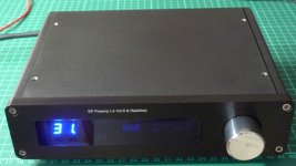
Well, someone has to break the ice, so here is my build just finished.
The preamp PCB does not come from this GB but from one organized in another forum. Still, it is the same PCB, made from the original Gerber files.
It is a build with a relay-switched attenuator, and as it stands on the front panel the latter is due to Jos van Einjdhoven:
RelaiXedPassive -- Documentation
His attenuator has been recently modified - I have the 2014 version but the attenuator part is the same.
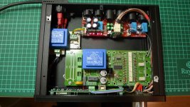
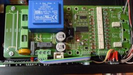
The second photo shows the overall arrangement of the components in the casing. The attenuator consists of two PCBs, and since it is meant to be built into a power amplifier it has a soft-start and a delayed switch-on power output, which in my case powers the preamp PSU. As such it is an overkill for this project, and I slightly modified it by disabling the soft-start circuit and retaining the delayed switch-on one.
I also had to modify the attenuator proper as well in order to adapt it for connection to the preamp. Firstly, it has four relay-switched RCA inputs which I do not need for this application, so I retained only two relays which now switch the channel selection relays on the preamp board. Secondly, changes were made to several of the attenuator PCB traces in order to adapt the circuit for the four-wire connection to the preamp.
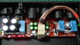
The preamp board is unchanged, but I had to make a small four-wire adapter board for the connection with the attenuator. The respective L and R reference (gound) connections are soldered to the J4 and J10 net-ties, as Hans Polak recently sketched, and taken all the way to the attenuator board. The cables used are RG179; the sole reason for this is the scarcity of fine microphone cables (Dia. < 2mm) on the market, unless one is ready to buy a 100m spool. The coax cable I used is not the easiest one to work with (Teflon insulation), and it took some work to make a proper connection. The six coax cable shields are grounded at one end only (at the preamp side), which required adding one small connector next to the channel switch one.
I've had no problems whatsoever at the first switch-on, and there is only barely audible noise from the loudspeakers at full preamp gain (6dB) and power amp gain of 26dB when the input is being fed digital zero from the music source.
There will measurements at a later date; what interests me primarily are the differences to the standard preamp model (with the volume pot in the NFB branch) that I've been listening to for more than one year now.
Regards,
Braca
Attachments
Last edited:
So in place of the pot in the NFB branch, you have a stepped ladder attenuator in the NFB branch?
That's I guess how Han's board works but you've managed it with some standard attenuator board which is great. Interesting too that you've used heatsinks on a few of the ICs.
I take it this is your main preamp now? How has it compared to any thing else you've tried?
Just got my Maya board and Han's board so it's now time to start building!
Last edited:
So in place of the pot in the NFB branch, you have a stepped ladder attenuator in the NFB branch?
That's I guess how Han's board works but you've managed it with some standard attenuator board which is great. Interesting too that you've used heatsinks on a few of the ICs.
I take it this is your main preamp now? How has it compared to any thing else you've tried?
Just got my Maya board and Han's board so it's now time to start building!
It would have been wonderful if I could have realized a stepped ladder attenuator in the NFB branch, but this topology is impossible with this type of attenuator. This attenuator is a replacement for a classical potentiometer volume control, and the Hans' board operates in the same manner. The NFB resistor sets the maximum gain of the final stage of the preamp, and in my case its value is 4K for the attenuator input impedance of 2K, resulting in the 6dB gain mentioned
I finished the preamp just two days before going to a trip, and there was very little time for listening to it (I'm now writing from a remote location, whereas the preamp is at home).
The first impression is that the sound has not changed in comparison with the previous BP preamp which has a Vishay conductive plastics pot in the NFB, but these are really just the first impressions.
I'll report some more after I've gathered more listening hours, and performed measurements on the unit.
I wish you success with your build.
Regards,
Braca
Last edited:
Han's board works in the NFB branch for sure - it selects pairs of resistors in place of the resistance of the two sides of the pot. It has been designed to never go open circuit.
Anything connected at the same point as the original pot will be in the NFB branch - looks like yours connects there too. Anything else would need to tap into a different point on the BPPBP board wouldn't it?
Anything connected at the same point as the original pot will be in the NFB branch - looks like yours connects there too. Anything else would need to tap into a different point on the BPPBP board wouldn't it?
Could the BPPBP be powered by a "SilentSwitcher" from Jan?
I looked at that. Not enough juice as far as I could see.
Could the BPPBP be powered by a "SilentSwitcher" from Jan?
No not without some modifications.
The Hypex controllers have an output between 11.5 to 12.5 Volt.
Dropout voltage is 3 Volt.
2 times 2.2 Ohm in series * 200mA = 0.9 Volt
Rectifier Diode: 0.6 Volt.
Add all together, and you will need worst case +/- 17 Volt input voltage, being 2 volts more.
Remove all rectifiers and 2.2 Ohm surge resistors, and you will still need +/- 15.5 Volt. Maybe this works, but it is on the edge, and you loose a safeguard protection for reversed input voltages.
Hans
Well you could also delete the Hypex regulators alltogether, and feed the BPBP from the SilentSwitcher +/-15. If you want to use a SS it doesn't make sense to also use the Hypex regs.
Jan
Jan
Well you could also delete the Hypex regulators alltogether, and feed the BPBP from the SilentSwitcher +/-15. If you want to use a SS it doesn't make sense to also use the Hypex regs.
Jan
Be aware in that case that the used relais can permanently withstand 15 Volt.
But there is no any other reason at all to restrict the voltage to +/- 12 Volt.
Hans
Be aware in that case that the used relais can permanently withstand 15 Volt.
But there is no any other reason at all to restrict the voltage to +/- 12 Volt.
Hans
Agree. I have a strong suspicion that the choice for 12V for the Hypex regs is (partly) driven by the relatively high dropout. If they would have gone for 15V, that would mean they needed like 20V input and that gets close for a 15VAC xformer + bridge rectifier and minimum mains voltage etc.
Most 12V relays can easily withstand 15 or even 18V, should not be an issue.
Jan
I will most certainly try the SS for the BPBP. Seems a perfect fit to me🙂
Hoping that GB3 for the BPBP will become reality soon.... or I could dig out the free PCB I got with Linear Audio🙄
Hoping that GB3 for the BPBP will become reality soon.... or I could dig out the free PCB I got with Linear Audio🙄
Han's board works in the NFB branch for sure - it selects pairs of resistors in place of the resistance of the two sides of the pot. It has been designed to never go open circuit.
Anything connected at the same point as the original pot will be in the NFB branch - looks like yours connects there too. Anything else would need to tap into a different point on the BPPBP board wouldn't it?
I've been away for a while, and now I'll try to explain why I see this solution as an attenuator at the last stage input.
In its native form, the stepped ladder attenuator is a potentiometer, albeit one that can not be wired directly as a replacement for the linear pot in the BP original circuit.
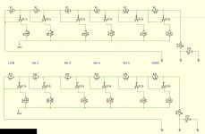
Referring to the Hans' circuit diagram in post #430 and concentrating on the left channel only, if all relays are engaged, i.e. resistors R1 to R6 are all short-circuited, the resistors R14 and R13 define an inverting amplifier with a gain of 2 (6dB). Now let RE1a change state such as shown in the circuit diagram, i.e. connecting R1 with R7. The result is a voltage divider R1/(R7\\R13) (wherein \\ is taken to mean "parallel") between the diff. stage output and GND1, feeding the series resistor R13 at the inverting input. The resulting gain is now 5dB, i.e. there is now an attenuation of -1dB relative to the previous configuration.
Thus this network needs four connection points with the preamp instead of three in the original circuit (GND1 is the fourth connection).
The above does not mean that the attenuator network is not a part of the NFB - it modifies the resistance in the input branch of the last stage. At the same time, the output of the diff. stage looks into a potential divider referred to GND1, which is different from the original circuit.
Having built this preamp with both versions of the volume control I can say that the one with the stepped attenuator is a clear winner as regards my needs.
Regards,
Braca
convert the BPPBP to a stepped switcher.
Hi all,
I promised some info to use a stepped switch instead of the Linear vol pot for volume control.
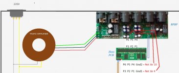
I adopted Hans Polak's sch (attachment sch) for the replacement of the vol pot and used his arrangement for attaching the switch to the Putzeys' PCB (attachment Net-Tie)
The Polak sch requires 4 connections for each channel. the extra connections are the GND and referred to as "Net Ties" 4 & 10. These Ties are quite small and have a very small land for a soldered attachment.
I suggest you make these two net tie 4 and net tie 10 early in assembly while you still have room to insert a soldering tip into the very limited space available there.
Referring to the Polak sch:
R14 is kept, I used 5k1 R14 is soldered onto the switch.
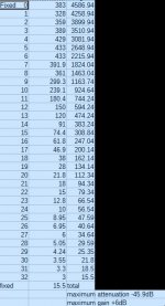
R13 and all the relays are replaced with a conventional ladder divider, but with very non standard values. The resistor values are shown in the second column of the attatchment. The 3rd column is the total value of the string from bottom to currently selected step and includes the 12r5 extra resistor (again soldered onto the switch) that sets the lowest volume (maximum attenuation)
Hi all,
I promised some info to use a stepped switch instead of the Linear vol pot for volume control.
I adopted Hans Polak's sch (attachment sch) for the replacement of the vol pot and used his arrangement for attaching the switch to the Putzeys' PCB (attachment Net-Tie)
The Polak sch requires 4 connections for each channel. the extra connections are the GND and referred to as "Net Ties" 4 & 10. These Ties are quite small and have a very small land for a soldered attachment.
I suggest you make these two net tie 4 and net tie 10 early in assembly while you still have room to insert a soldering tip into the very limited space available there.
Referring to the Polak sch:
R14 is kept, I used 5k1 R14 is soldered onto the switch.
R13 and all the relays are replaced with a conventional ladder divider, but with very non standard values. The resistor values are shown in the second column of the attatchment. The 3rd column is the total value of the string from bottom to currently selected step and includes the 12r5 extra resistor (again soldered onto the switch) that sets the lowest volume (maximum attenuation)
Attachments
Last edited:
the range can be changed to -52dB to +0dB by adding one resistor.
This resistor could be switched in parallel with R14, or can be soldered in for a fixed range.
The switched parallel resistor would be handy for using low output voltage sources that require the +6dB gain and all other sources would use the low gain version (operationally like a Buffer).
This resistor could be switched in parallel with R14, or can be soldered in for a fixed range.
The switched parallel resistor would be handy for using low output voltage sources that require the +6dB gain and all other sources would use the low gain version (operationally like a Buffer).
- Home
- Source & Line
- Analog Line Level
- BPPBP - Bruno Putzey's Purist Balanced Preamp (well a balanced volume control really)