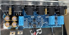
My BPPBP build just got an improved power supply:


That build originally used a small screened toroidal transformer with a single 230V primary. I wanted to convert it to 115/230V primary and made some measurements first. The toroid turned out a tightly coupled, wide band device (see the measurements below), so I replaced with an UI core transformer (somewhat oversized, but I had it at hand) with an additional passive input filter, based on the design of my power supply for the Omicron headamp:

Also, I added a small rectifier for the "power on" LED and RC snubbers on the secondaries.
The common mode suppression is much improved (pink is the amplitude, red is the phase):

and so is the differential mode suppression (here, without rectifier/filter/regulator/load):

That build originally used a small screened toroidal transformer with a single 230V primary. I wanted to convert it to 115/230V primary and made some measurements first. The toroid turned out a tightly coupled, wide band device (see the measurements below), so I replaced with an UI core transformer (somewhat oversized, but I had it at hand) with an additional passive input filter, based on the design of my power supply for the Omicron headamp:
Also, I added a small rectifier for the "power on" LED and RC snubbers on the secondaries.
The common mode suppression is much improved (pink is the amplitude, red is the phase):
and so is the differential mode suppression (here, without rectifier/filter/regulator/load):
Sorry, Impressive images, but to be honest I have a problem in understanding what you are showing.
DM and CMSR of what, from primary input to J1 ?
And did you add the signal on top of the mains supply ?
Would measuring on the preamps DC supply not be more revealing while injecting a signal on the mains supply ?
Hans
DM and CMSR of what, from primary input to J1 ?
And did you add the signal on top of the mains supply ?
Would measuring on the preamps DC supply not be more revealing while injecting a signal on the mains supply ?
Hans
Hans,
The charts show CM and DM rejection from AC mains input to J6, which is the input of the power supply rectifier:

Since my mains filter is entirely passive, I measured its small signal transfer characteristics, without the actual mains connected.
Measuring the DC supply rails might be more revealing for the DM rejection, but IMO DM here is not so important or interesting. The DM signal after the power transformer is attenuated by 2x RC (2R2+1000uF) filters, each adding about 40dB of rejection above 10kHz, and by the regulator, which in case of HxR12 adds as much as 110dB below 10kHz. Then there is the opamps' PSRR between the supply rail and the preamp's output. Summing up, I wouldn't worry so much about DM, and I doubt I would be able to accurately measure that kind of ripple rejection while adding the test signal on top of the live mains supply.
CMRR is a bit more interesting, as J6 is the supply rail in this case; neither the RC filters nor the regulators add anything to CMRR. The sonic value of additional CM rejection of course depends on things outside the prepamp, such as the signal source and interconnects. BPPBP's own CMRR may not be astronomical in some cases (see my measurements of a similar circuit), so I thought adding a few passives to help it is worthwhile.
The charts show CM and DM rejection from AC mains input to J6, which is the input of the power supply rectifier:
Since my mains filter is entirely passive, I measured its small signal transfer characteristics, without the actual mains connected.
Measuring the DC supply rails might be more revealing for the DM rejection, but IMO DM here is not so important or interesting. The DM signal after the power transformer is attenuated by 2x RC (2R2+1000uF) filters, each adding about 40dB of rejection above 10kHz, and by the regulator, which in case of HxR12 adds as much as 110dB below 10kHz. Then there is the opamps' PSRR between the supply rail and the preamp's output. Summing up, I wouldn't worry so much about DM, and I doubt I would be able to accurately measure that kind of ripple rejection while adding the test signal on top of the live mains supply.
CMRR is a bit more interesting, as J6 is the supply rail in this case; neither the RC filters nor the regulators add anything to CMRR. The sonic value of additional CM rejection of course depends on things outside the prepamp, such as the signal source and interconnects. BPPBP's own CMRR may not be astronomical in some cases (see my measurements of a similar circuit), so I thought adding a few passives to help it is worthwhile.
Last edited:
@Hans Polak Sorry to dig this up, but in Post #985 you offered to send the algorithm for your Encoder/Relay-based substitution for the Potentiometer. I dug through most of this thread and feel, this is still the most debated part of the whole circuit 😉
I'm currently working on a way to include the BPPBP into a professional audio/mastering-context, where I'd need steps of 0.5dB between -6 and +6dB. Not the usual hifi-range ... As I'm fairly new to the forum and more of a learner/reader, I'm not able to send you a DM to ask you for your algorithm, so this is the way. Thank you!
btw, thank you for your contributions, along with @alexcp , who's PCB I'm currently using!

The algoritm is very simple, make the volume change in two steps.
Step 1: switch all relays that have to change from 1 to 0 immediately
Step 2: switch the relays that have to go from 0 to 1 after the relay’s settling time, which is usually something like 4 to 5 msec.
So going from 011111 to 100000 first goes to 000000 and after 5msec to 100000
Going from 100000 back to 011111 first goes to 000000 and after 5 msec to 011111.
The step in between completely prevents any glitches and happens too fast to notice the step in between.
Hans
Thank you! I will actually solve this with a make-before-brake mechanical encoder as I would like to avoid any digital circuits. But how are the resistor networks calculated? I'm a bit stuck:The algoritm is very simple, make the volume change in two steps.
Step 1: switch all relays that have to change from 1 to 0 immediately
Step 2: switch the relays that have to go from 0 to 1 after the relay’s settling time, which is usually something like 4 to 5 msec.
So going from 011111 to 100000 first goes to 000000 and after 5msec to 100000
Going from 100000 back to 011111 first goes to 000000 and after 5 msec to 011111.
The step in between completely prevents any glitches and happens too fast to notice the step in between.
Hans
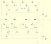
Referring to the attached schematic of your An alternative Volume Controller for the Bruno Putzeys balanced Pre Amp:
R12(22) is Rf of the last OPAmp-stage, R10(21) is Rs. R12/R10 sets a gain of 2 = 6dB. The Resistor Network is a L-Pad attenuator before that. But is it really? Or should it be treated like a T-Pad? Or am I completely off?
Short: I'm stuck, calculating custom values for the Resistor Array and would be grateful for some explanation how to approach it.
Timm
Attachments
I dont think you will get anything above 0 dB as there is no positive gain in that design of Brunos.
//
//
Actually there is plenty. Check the last inverting opamp. If you refer to the schematic I just posted, it's just a snippet/modification for the whole BPPBP.I dont think you will get anything above 0 dB as there is no positive gain in that design of Brunos.
As of my question, I think I figured it out and would ask you, @Hans Polak just to confirm:
R1 and R2 etc. form a L-Pad which attenuates/compensates/adapts the +6dB created via R12/R10, so actually the gain of the opamp stays constant, there is just passive attenuation happening before that.
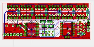
Does anyone has a set of the files (gerbers and schematic). The high rez version is not longer available in edn. Tks
I have found decent gerbers ( I want to look at them, not to order), but so far no schematic.
I have found decent gerbers ( I want to look at them, not to order), but so far no schematic.
Last edited:
Just in case the file is finally deleted from Hypex's download area. I think this article deserves to continue being available.
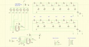
Thank you Bruno for an insightful article and an excellent circuit. My personal implementation of this circuit and its layout differs only in inserting an MAS6116 digital volume controller in place of the potentiometer.
Thank you Bruno for an insightful article and an excellent circuit. My personal implementation of this circuit and its layout differs only in inserting an MAS6116 digital volume controller in place of the potentiometer.
Attachments
Hi @Hans Polak would it be possible to share the documents again, please? I’ve built a BPPBP recently and next I want to dig into the 64 step volume control but have no available documentation nor did I find any available PCBs. But I guess what with the proper documentation including a gerber, I would be able to go on that route.Here is everything you would need for the manual and the remote volume control, as well as the 4 input extension. Dropbox - Zipped - Simplify your life
Do with it as you like.
Succes,
Hans
I’m still very noob in electronics but I can understand basics and if I built the Bruno, I guess a volume control wouldn’t be much more complicated 🙂
This looks amazing. Are there any changes one could obtain this Zoja audio relay attenuator adapter for the BPPBP? While im interested in Hans’ 64 step attenuator, I’m still evaluating other options that could make it easier for me.BPPBP(BP Preamp LA vol.5) & Audio Relay Attenuator Zoja
Here is one BPPBP integrated with the Zoja audio relay attenuator that is the fruit of our local forum.ARA Zoja has a remote control, is based on a bluepill plate and is adapted for BPPBP. Attenuation is done with 6 relays (-63db) and the seventh relay is for the MUTE function. It also has an output for a POWER relay as well as a channel selector (CH1/CH2). With the help of an adapter plate that is soldered instead of a potentiometer to the BPPBP connection is made with two balanced microphone cables of 3mm.
Thanks!
Thank you very much, Hans. Much appreciated. I will most probably reach out if I don't find what I need in this forum.
I have managed to successfully build the 64 step potentiometer and control it via arduino with an IR remote. It still is in a development phase as I also want to add mute/unmute function and use a bigger display. So thanks @Hans Polak for the files!
Nonethless I have some stupid questions and to relate a stupid thing I did 🙂
Note I do not have advanced electronics knowledge, so it is not surprising that I do stupid things.
So, I have finished the bruno preamp a few weeks back. Got the pcbs from hifiocean, got the parts, soldered with a hot air gun, all good and working. Later I replaced the LM4562 with OPA1656, still good.
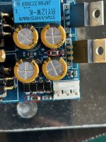
All this period I have powered the board either from 2* 12VDC power supplies that I got from some chinese LED bands, and lately from 2 * UPS batteries. Now the stupid thing: I have powered it with 12VDC at J6, not considering that there will be a voltage drop from the diodes (as I understand that is about 0.7V *2) and from the voltage regulators (as I understand that can go up to 2V).
Surprinsingly it went very well for about 100 hours I'd say. But, one day when a friend of mine was using it all of a sudden the music stopped, he heard a click in the speakers and then a bit of some coming out from the high current resistors in the power supply part.
I noted that R25 and R28 look "tanned".
What could've gone wrong? Since it worked well for a long time and all of a sudden the outcome looks like the result of short circuit, or something causing the circuit to draw excessive current.
Another question is: what is the reason for K3 being on the output stage? From the schematic and board it looks like it's shorting pins 2 and 3 of the output when not powered, or maybe I've not observed well.
I didn't have the time yet to desolder and start checking components individually so I thought maybe I can get some pointers here before doing something.
Any help is much appreciated.
Nonethless I have some stupid questions and to relate a stupid thing I did 🙂
Note I do not have advanced electronics knowledge, so it is not surprising that I do stupid things.
So, I have finished the bruno preamp a few weeks back. Got the pcbs from hifiocean, got the parts, soldered with a hot air gun, all good and working. Later I replaced the LM4562 with OPA1656, still good.
All this period I have powered the board either from 2* 12VDC power supplies that I got from some chinese LED bands, and lately from 2 * UPS batteries. Now the stupid thing: I have powered it with 12VDC at J6, not considering that there will be a voltage drop from the diodes (as I understand that is about 0.7V *2) and from the voltage regulators (as I understand that can go up to 2V).
Surprinsingly it went very well for about 100 hours I'd say. But, one day when a friend of mine was using it all of a sudden the music stopped, he heard a click in the speakers and then a bit of some coming out from the high current resistors in the power supply part.
I noted that R25 and R28 look "tanned".
What could've gone wrong? Since it worked well for a long time and all of a sudden the outcome looks like the result of short circuit, or something causing the circuit to draw excessive current.
Another question is: what is the reason for K3 being on the output stage? From the schematic and board it looks like it's shorting pins 2 and 3 of the output when not powered, or maybe I've not observed well.
I didn't have the time yet to desolder and start checking components individually so I thought maybe I can get some pointers here before doing something.
Any help is much appreciated.
Attachments
- Home
- Source & Line
- Analog Line Level
- BPPBP - Bruno Putzey's Purist Balanced Preamp (well a balanced volume control really)