Here you go. It's missing the input switch pieces of code, I still have to add them from the project I got from Hans. Also note I was using a display that has the same I2C address as the second NXP chip; still waiting on the new display that has a different address.
Enjoy!
Enjoy!
Attachments
R25 to R28 are too small.
They should be replaced by 0.5watt Beyslag resisistors.
This was already mentioned in the start of the project.
The relay at the output is to supress spikes in the output at power on
Hans
They should be replaced by 0.5watt Beyslag resisistors.
This was already mentioned in the start of the project.
The relay at the output is to supress spikes in the output at power on
Hans

The 2R2 resistors are being taken out by the inrush current which is doing the initial charging of the large smoothing capacitors in the power supply section as you power it up. I had the same issue when I first built this circuit. The original Bruno Putzeys article specifies R25.26.27,28 as 2R2 1206 high current. I had issues getting hold of sufficiently robust resistors and simply replaced mine with wire links. All remains working fine after a few years regular use.
As far as K3 in the output circuitry, this is shorting the output until power is applied or as power is lost.
As far as K3 in the output circuitry, this is shorting the output until power is applied or as power is lost.
Thank you very much Hans and geoff. i could swear I read at least half of the thread and either didn't notice or forgot about this aspect.
I did install Panasonic 1206 high current 0.66watt (https://ro.mouser.com/ProductDetail/667-ERJ-P08J2R2V) and they still died. I was thrown off by the fact that it did work properly for a long time.
But if I'll just use a Ian Canada linearpi dual mk2 and set it to dual 12V, then i should be ok to bypass the rectification and just power at U4 and U5 OUT and GND. Basically take out the regulators and plug in the linearpi. Might be overkill but I like the quality of Ian's power supplies.
The idea of the 2R2 resistors is to provide a little extra filtering. In combination with the smoothing capacitors they form a low pass RC filter. Taking them out of circuit and replacing them with wire links only has a small effect on the dc supply prior to the voltage regulators. I would be surprised to see much at all impact on any residual ripple remaining as seen by the op-amps. Just use what you have already but with the wire links in place of the 2R2 resistors - there's no need to replace what you already have with anything else.
Sorry, but I can’t agree with the idea of replacing resistors by wires.
The reason the resistors are fried is because of the high inrush current into the large caps.
Replacing the resistors will alow even higher inrush currents, potentialy fatal for the caps when using batteries that can easily supply very large currents.
Hans
The reason the resistors are fried is because of the high inrush current into the large caps.
Replacing the resistors will alow even higher inrush currents, potentialy fatal for the caps when using batteries that can easily supply very large currents.
Hans
Thanks @geoffw1 but I am not comfortable with using the batteries on a long term as they have to be charged from time to time and I’m a very comfortable person 🙂 I prefer spending 150 usd on a good linear power supply and just push a button when I want to enjoy music. Ian’s power supplies are pretty clean afaik and I believe an RC or CRC filter won’t add much value anyway. Same for regulators.
@Hans Polak thanks for the info. If I bypass the whole rectifier, filter and regulator part and just plug in a good quality 12v power supply like I was planning to, wouldn’t it work? I can still add some resistors in series with the DC power supply to protect the circuit from inrush current. Some through hole or MLF vishay beyschlag (hope I can find 0.5w, I saw mouser only has 1w, 0.4w or less).
Wouldn’t it be ok?
I want to bypass diodes and regulators because of the voltage drop and lack of need if I a good linear regulated DC PS. The linearpi is rated at 12V 2A.
If you are planning on running on batteries, I would certainly agree with Hans on needing the resistors.
If you're running off a transformer + bridge rectifier, I wouldn't agree. Looking at supplies designed by a number of well respected guys (Doug Self, Bonsai, etc.), the resistors are absent.
If you're running off a transformer + bridge rectifier, I wouldn't agree. Looking at supplies designed by a number of well respected guys (Doug Self, Bonsai, etc.), the resistors are absent.
The best way to decide what to do is simply by listening.
Preamps IMO are quite sensitive to different sorts of supplies.
I settled on using the 12V Hypex regulators and keeping the diodes and caps intact.
But feeding the circuit from batteries instead of a mains transformer or even from external 18Volt regulated supplies gave an obvious improvement to my personal taste.
And yes, 0.4Watt Beyschlags are perfectly O.K.
Hans
Thank you both. I agree that preamps are sensitive to different sorts of supplies and I have noticed very good performance on batteries.
I’ve had good experiences with Ian’s supply for the dac, which somehow gave better results for that project for my taste. So I want to try it with the preamp too.
This is what I want to use - https://github.com/iancanada/DocumentDownload/blob/master/LinearPi/LinearPiMkIIUsersManual.pdf
Ive seen others on this forum bypassing the regulators and plugging a good linear power supply. I don’t think it will be a problem if it’s well made.
I’ll order some resistors too.
If I don’t like the results I guess I’ll go back to batteries. Maybe find a LiFePO solution.
Very impressive supplies from Ian, also the Li battery option, thx for sharing.
Wasn’t come across these before.
Hans
Wasn’t come across these before.
Hans
You’re welcome. Yes the Li battery option is really nice. So the linear one I’m betting doesn’t need any more filtering or regulation. At most 2 of those 0.4 watt. Although if I read correctly the linear supplies have soft start.
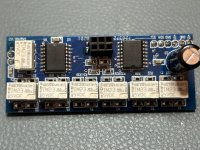
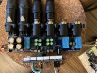
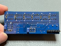
I've finally received the PCB boards for the 64 steps volume control. I've assembled one of them and and installed IM23TS relays from TE Connectivity, Panasonic ERA 0805 thin film resistors, Nexperia BAS316 diodes (same one used for the Bruno Preamp's relays), headers. Managed to program an arduino nano to control the PCF chip and change volume. Connected to the preamp and..surprise, I have issues that I can't figure out.
I'm using an IR remote and sensor to control the attenuation steps. I'm starting at max attenuation (0x3F) and rise towards 0. My arduino code is based off of alexcp's sketch.
Issue #1 - noise. Sounds like groundig noise. I did connect the boards GND1/ 2 to the preamp net tie J4/10 as per Hans' document.
Issue #2 - switching clicks and pops. There are audible clicks when changing attenuation levels. More proeminent (tweeter endangering levels) when I switch from step 32 to 31 and then back to 32. I have tried the 2 step approach as suggested by Hans in post #1086 without luck. It pops even more when I reach step 25 and from there at every step towards 0.
I did a brief measurement at P1 to P6 and it does seem that around step 32 the impedance jumps from 4.xx to 3.9x and then back to 4.xx on the next steps towards 0. This is awfully strange, I would expect impedance to go up and down progressively as I change attenuation.
Issue #3 - there's no music when I feed signal to the input. When the source signl is very low, I can't hear anything. If I start turning the source's volume knob, oh boy robots and crackles start to be heard in the speakers. Like really loud crackles and noises. Did I by any chance connect P1-P6 in a wrong way to the preamp board?
I've attached some pictures and my arudino sketch maybe it helps someone help me a bit here. I'm stuck.
Thanks!
NOTE: I haven't connected anything to earth ground, as the preamp and amplifier ( an Ice power stereo module) are not in a case yet. The issues above do not reproduce when using a normal pot (linear or log).
Attachments
Last edited:
Issue 2:
The code you uploaded in your last post no longer implements Hans's suggestion from post #1086. Its currently commented out. I suggest it didn't work for you as you have set a delay of 20ms (way too long).
The code you uploaded in your last post no longer implements Hans's suggestion from post #1086. Its currently commented out. I suggest it didn't work for you as you have set a delay of 20ms (way too long).
I suggest you reinstate the code with the delay set as per Hans's instructions. After all, he should know best how this stepped network functions:void setAttenuation(byte attenuation) {
/* // Step 1: Switch all relays to '0' (max attenuation)
Wire.beginTransmission(VOLCB_ADDR); // Start transmission to device
Wire.write(0x3F); // Send max attenuation value (all relays off)
Wire.endTransmission(); // End transmission
Serial.println(F("All relays switched to 0 (max attenuation)"));
delay(20); // Wait for the relay's settling time, 4 to 5 milliseconds
*/
// Step 2: Apply the desired attenuation level after settling time
void setAttenuation(byte attenuation) {
// Step 1: Switch all relays to '0' (max attenuation)
Wire.beginTransmission(VOLCB_ADDR); // Start transmission to device
Wire.write(0x3F); // Send max attenuation value (all relays off)
Wire.endTransmission(); // End transmission
Serial.println(F("All relays switched to 0 (max attenuation)"));
delay(5); // Wait for the relay's settling time, 4 to 5 milliseconds
// Step 2: Apply the desired attenuation level after settling time
Thanks @geoffw1 that was only a test. I had initially tried with 5ms but still didn't work.
So issues #1 and #3 were because I had connected the board opposite to how it should. Hans had attached a schematic in post #427 but I missed it. Having the connections done properly, it works well. So I get the prize for lack of attention and stupid
Issue #2 still persists.
I have reinstated the code as suggested, using the 5ms delay. Turning all relays to 0, which ix 0x00 (right?) creates a more than distrubing click in the speakers.
If I turn them to 1, though, the clicks are less audible but they get louter as I progress towards 0 attenuation.
Here's the updated piece of code:
void setAttenuation(byte attenuation) {
// Step 1: Switch all relays to '0' (max attenuation)
Wire.beginTransmission(VOLCB_ADDR); // Start transmission to device
Wire.write(0x00); // Send max attenuation value (all relays off)
Wire.endTransmission(); // End transmission
Serial.println(F("All relays switched to 0 (max attenuation)"));
delay(5); // Wait for the relay's settling time, 4 to 5 milliseconds
// Step 2: Apply the desired attenuation level after settling time
Wire.beginTransmission(VOLCB_ADDR); // Resume transmission to device
Wire.write(attenuation); // Send the desired attenuation value
byte transmissionResult = Wire.endTransmission(); // End transmission and check for success
// Print the results for debugging
Serial.print(F("Transmitting data to volume control: "));
Serial.print(attenuation, HEX); // Print the attenuation value in hexadecimal
Serial.print(F(" - Transmission result: "));
Serial.println(transmissionResult == 0 ? "Success" : "Failed");
}
Well done on sorting issues 1 and 3 out! As far as the remaining issue 2, it may well be worth persisting with Hans's procedure but try it with various values for the delay. Its probably simply a case of tuning the routine to suit the relays you have.
For my own implementation of Bruno's pre-amp, I've used an MAS6116 digital volume control chip. This effectively does the same as Han's circuit but using solid state switching of a resistor network, all within the same chip. That's similar to what alexcp has on offer on his site but mine is an smd design. The plus for this is it has zero crossing detection / switching to provide click free volume adjustments at 0.5dB interval and a mute function.
For my own implementation of Bruno's pre-amp, I've used an MAS6116 digital volume control chip. This effectively does the same as Han's circuit but using solid state switching of a resistor network, all within the same chip. That's similar to what alexcp has on offer on his site but mine is an smd design. The plus for this is it has zero crossing detection / switching to provide click free volume adjustments at 0.5dB interval and a mute function.
Interesting option. I did look at MAS6116 in the past but somehow I decided to take the route with Hans' relay board. It's a bit late to pivot now and start learning how to use that one as I admit looks a bit complicated to me (beginner in these things).
I'll keep trying, maybe @Hans Polak can chime in when he sees this.
I'll keep trying, maybe @Hans Polak can chime in when he sees this.
I've a spare board or two if you're interested. The board doesn't contain PSU or source select as I have them on separate pre-existing boards. Code to run it from an Arduino Nano along with rotary encoder, remote IR, source select and LCD display is already done. The whole setup works really nice and acoustically would take some beating. As described elsewhere, its a piece of string with amplification!
The only improvement I'm working on at present is to update my controller / display to use a TFT display controlled from an ESP32. Controller board, display and code are all done + tested. I'm just waiting for my new front panel machined to take the display /controller board.
The only improvement I'm working on at present is to update my controller / display to use a TFT display controlled from an ESP32. Controller board, display and code are all done + tested. I'm just waiting for my new front panel machined to take the display /controller board.
Last edited:
Thanks Geoff, that sounds really nice. I'll get back to you for sure if I don't succeed with this. It does sound like a good alternative with not much effort involved (I can certainly put things together but definitely not an advanced DIYer).
- Home
- Source & Line
- Analog Line Level
- BPPBP - Bruno Putzey's Purist Balanced Preamp (well a balanced volume control really)