Hi DirkLeh !
I have been wiring only one 10 Ohms resistor as R302 on the printed circuit, just like on the schematic (and only one 10 Ohms resistor is given with the kit ...).
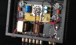
And i have been changing a bit the place of the choke, i shall take pictures later !
Gidu
I have been wiring only one 10 Ohms resistor as R302 on the printed circuit, just like on the schematic (and only one 10 Ohms resistor is given with the kit ...).
And i have been changing a bit the place of the choke, i shall take pictures later !
Gidu
Hi Gidu,
I struggled with the schematics there. It shows only one 10R, but nominates R301 to 303 and the picture from Boyuu shows two on the PCB and one in series from the valve to the PCB.
Maybe someone else can shed some light on that, before you roast something on the amp. Mine runs with three resistors.
Please see attached picture.
Attachments
Hi !
But what is the value of each résistance ? I think the value of the equivalent resistance of the three resistors serialization must be 10 Ohms, it would make sense according to the diagram. But this remains to be confirmed ...
Gidu
But what is the value of each résistance ? I think the value of the equivalent resistance of the three resistors serialization must be 10 Ohms, it would make sense according to the diagram. But this remains to be confirmed ...
Gidu

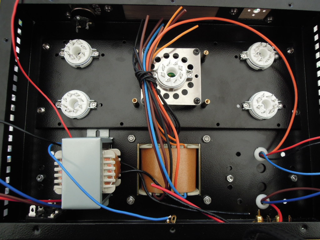
In fact, the choke inductor is mounted on the chassis as in the pictures above ! I have been using a hole for fixing the cover of the output transformer and the other leg of attachment of the choke is inserted under the plate which carries the supports of the electronic tubes.
Gidu
Last edited:
Anybody out there who could emlighten us on the resistor value/number for the R301/303 just after the rectifier tube before the choke.
Since no expected voltages are provided for either B1 or B2, it could be anything.
I inserted 3 resitors with 10R each, i.e. 30R before the choke.
Any hints, guys?
Since no expected voltages are provided for either B1 or B2, it could be anything.
I inserted 3 resitors with 10R each, i.e. 30R before the choke.
Any hints, guys?
Hi !
To DirkLeh : Does your A9 operate normally with 301/303 R = 30 ohms? Do you have an audible buzz or hum?
I ordered 1 set of Electro-Harmonix tubes (EL34 x 2, 5U4GB and 6SN7 x 2) to replace the original Chinese tubes and I will also replace the C302 filter capacitor 150 microfarads with a 330 microfarads. I will also add two 220 Ohms resistors to create a point virtual environment on 6SN7 heating power to reduce the buzz. I'll also probably insert a resistor between the volume potentiometer slider and grid 6SN7 (10K grid stopper resistor, like suggested by Digg-it).
Gidu
Last edited:
Hi !
To DirkLeh : Does your A9 operate normally with 301/303 R = 30 ohms? Do you have an audible buzz or hum?
Gidu
Define normally.
Yes mine runs with the 30R, but I have some hum. With the original chinese preamp tubes hum is accetable. I did replace all tubes with a German made 5U4G and replaced the EL34B with a TungSol. After I replaced the preamp tube with NOS 6SL7GT (Russian Military) I had incredible hum and went back. Apparently the Russian tubes don't like AC heating. Tried the grid-stopper resistor, but made no difference. What I also did was replace the dodgy switch with a Lorlin and the crackly potentiometer with an Alps RK27, much better now.
I don't have the gear to measure power or frequency response, so have to rely on my ears only. Thought about DC heating, but my voltage is too high to rectify and toast the filaments out of range.
I also added another 150uF cap parallel to the one in the power supply for more filtering. That also reduced hum a little. All in all not too bad, but the preamp tubes are still on the board for replacement. All the other tubes brought a major improvement.
Keep posted on your progress and findings!
Dirk
I will also add two 220 Ohms resistors to create a point virtual environment on 6SN7 heating power to reduce the buzz.
Gidu
How and why do you add the two resistors on the preamp tube heating??
Why does that reduce buzz?😕
How and why do you add the two resistors on the preamp tube heating??
Why does that reduce buzz?😕
Hi !
Take a look at the schematic at the Botton of this page : Alimentation filaments sur le forum Discussions Générales du site Homecinema-fr.com - 29942556 - 1472
But, sorry, this thread is in french ...
Gidu
For example, look here, too :
And here :
Gidu
And here :
An externally hosted image should be here but it was not working when we last tested it.
Gidu
Last edited:
Hi!
I changed the filter capacitor ( 150 microfarads to 330 microfarads - 450 Volts ) and I added two 100 Ohm resistors to balance the heating line of 6N9PJ tubes connected to the chassis ground.
Finally, I added a grid resistor of 3.3 kilo ohm on 6N9PJ tubes.
The buzz has totally disappeared, only a very slight hum subiste heard only if the ear is glued to the speakers ... It's almost perfect !
Here are pictures of the mods :
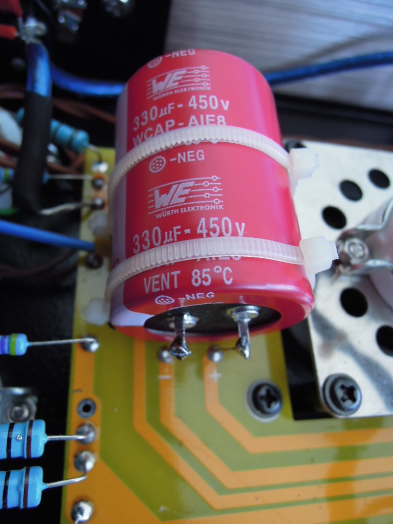
Nouveau condensateur de filtrage : 33 microfarads 450 Volts
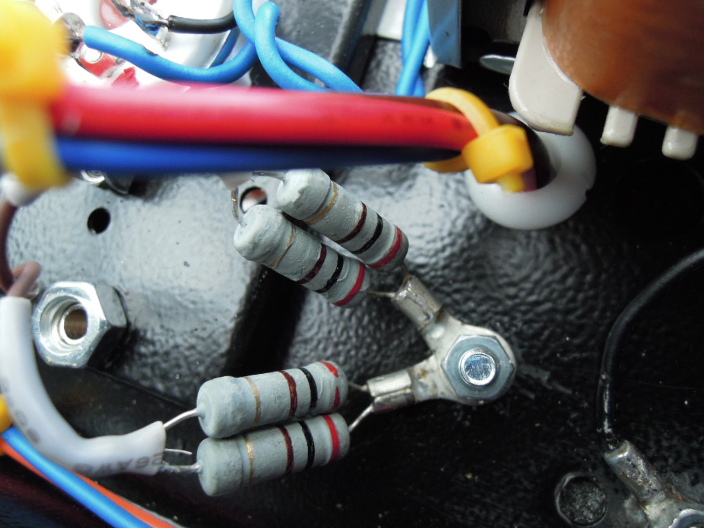
Résistances d'équilibrage du 6,3 Volts de chauffage des filaments des 6N9PJ (2 x 200 Ohms en //)
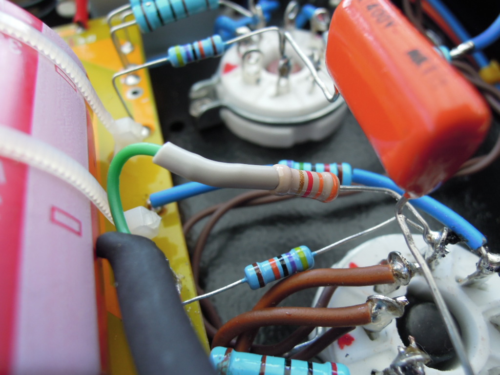
Résistance de grille de 3300 Ohms et connection des deux résistances d'équilibrage sur le 6,3 Volts
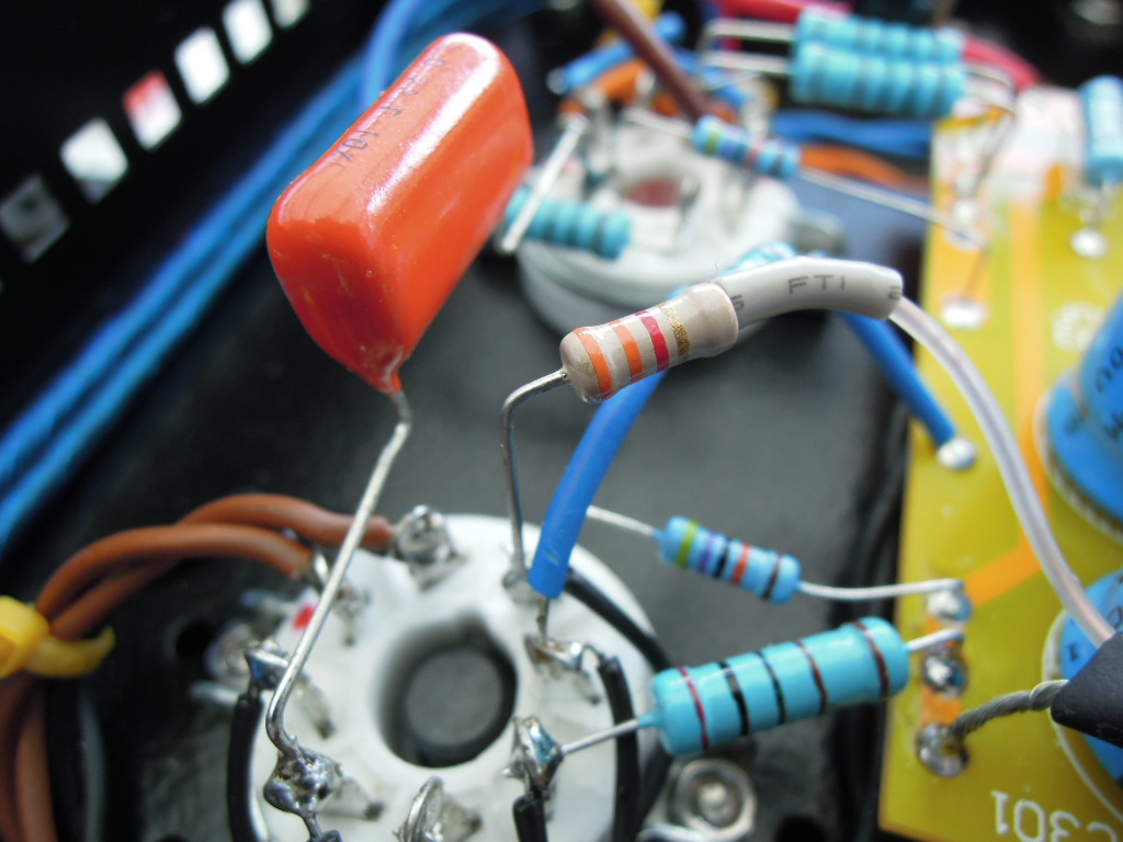
2ème résistance de grille de 3300 Ohms et connection des deux résistances d'équilibrage sur le 6,3 Volts
That's all for today !
Gidu
I changed the filter capacitor ( 150 microfarads to 330 microfarads - 450 Volts ) and I added two 100 Ohm resistors to balance the heating line of 6N9PJ tubes connected to the chassis ground.
Finally, I added a grid resistor of 3.3 kilo ohm on 6N9PJ tubes.
The buzz has totally disappeared, only a very slight hum subiste heard only if the ear is glued to the speakers ... It's almost perfect !
Here are pictures of the mods :
Nouveau condensateur de filtrage : 33 microfarads 450 Volts
Résistances d'équilibrage du 6,3 Volts de chauffage des filaments des 6N9PJ (2 x 200 Ohms en //)
Résistance de grille de 3300 Ohms et connection des deux résistances d'équilibrage sur le 6,3 Volts
2ème résistance de grille de 3300 Ohms et connection des deux résistances d'équilibrage sur le 6,3 Volts
That's all for today !
Gidu
Last edited:
Have you removed the B3 connection to the 6n9p filaments?
You don't want to be using both heater elevation and artificial centre tap to ground.
You don't want to be using both heater elevation and artificial centre tap to ground.
Well, i don't have any connection between B3 and the 6N9P filaments (your schematic is different from mine) ... I only have now artificial center tap to ground !
Gidu
Gidu
Last edited:
Here is the simple schematic of this mod (this is just an example) :
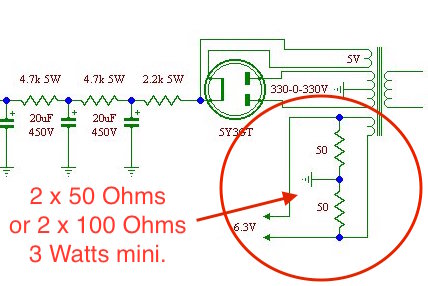
The resistors can be replaced by a wound potentiometer 100 Ohms / 3 Watts , allowing fine-tune balancing of 6.3 Volts.
(The current through the resistors is: I = 6.3 / 100 = 0.063 mA , so the power dissipated is: P = 0,063 x 63 = 0.396 Watts or P = 6,3 x 6,3 / 100 = 0,396 Watts)
PS : Warning to the mount of the new 300 microfarads capacitor : its diameter is 30 mm , so mounting is not possible if you use the spacers provided with the kit to secure the PCB ! See specifications of this capacitor here : http://www.conrad.fr/ce/fr/product/1281198/Condensateur-electrolytique-Wuerth-Elektronik-861221485017-Snap-In-10-mm-330-F-450-V-20--x-h-30-mm-x-41-mm-1-pcs/SHOP_AREA_17428
Gidu
Last edited:
Sorry, assumed your kit was the same as the first schematic posted on this thread which has a B3 supply elevating the heater
I received and installed my new tubes : EL34 EH , 5U4GB EH and 6SN7 EH.
I have no buzz and A09 works perfectly!
It remains for me to have the patience to let these tubes lapped slowly ... but for now , the sound is already very satisfying !
Gidu
I have no buzz and A09 works perfectly!
It remains for me to have the patience to let these tubes lapped slowly ... but for now , the sound is already very satisfying !
Gidu
Hi Gidu,
Just wondering....
Wasn't the replacement for the 6N9P actually the 6SL7 as opposed to the 6SN7?
The two have entirely different characteristics (amplification, resistance)!
Strange that they apparently work for your configuration on the A9 kit, or did you make further changes?
I will give this resistor mod of yours on the heating supply a chance and see if that makes a difference for mine.
Will report.
Hi DirkLeh !
yes, you're right : i made a mistake, the exact equivalent for the 6N9P is effectively the 6SL7. So i did take off the 6SN7 to replace it by the 6N9P ...
Gidu
yes, you're right : i made a mistake, the exact equivalent for the 6N9P is effectively the 6SL7. So i did take off the 6SN7 to replace it by the 6N9P ...
Gidu
... But it worked perfectly, I still even replaced the 6N9P because, after verification, the value of the 6SN7 heating current is twice the 6N9P (600 mA instead of 300 mA), which for two tubes carries the filament heating current to 1.2 Ampères while the maximum current debited by winding heating 6N9P supply transformer is 1 A !
Gidu
Gidu
- Home
- Amplifiers
- Tubes / Valves
- Boyuu EL34 A9 Tube Amp