Hi!
Here are my latest mods :
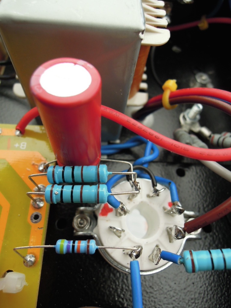
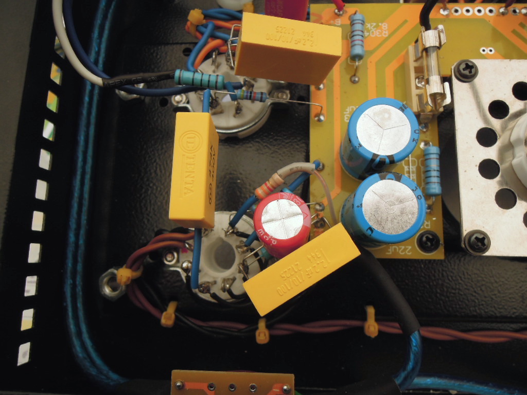
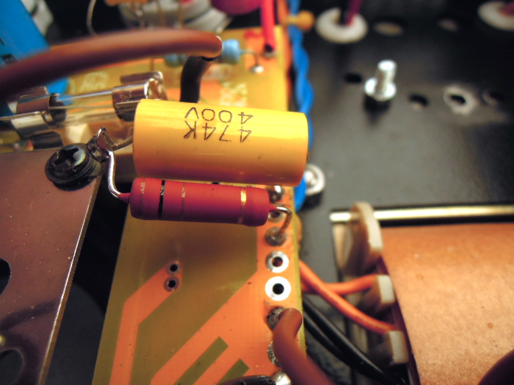
- I replaced the 0,22μF link capacitors by 0,47μF 400 volts MKP, and i also replaced the electrolytic capacitors that I added a few days ago, to decouple the 6N9PJ cathode resistors by high-quality 40Volts 470μF capacitor,
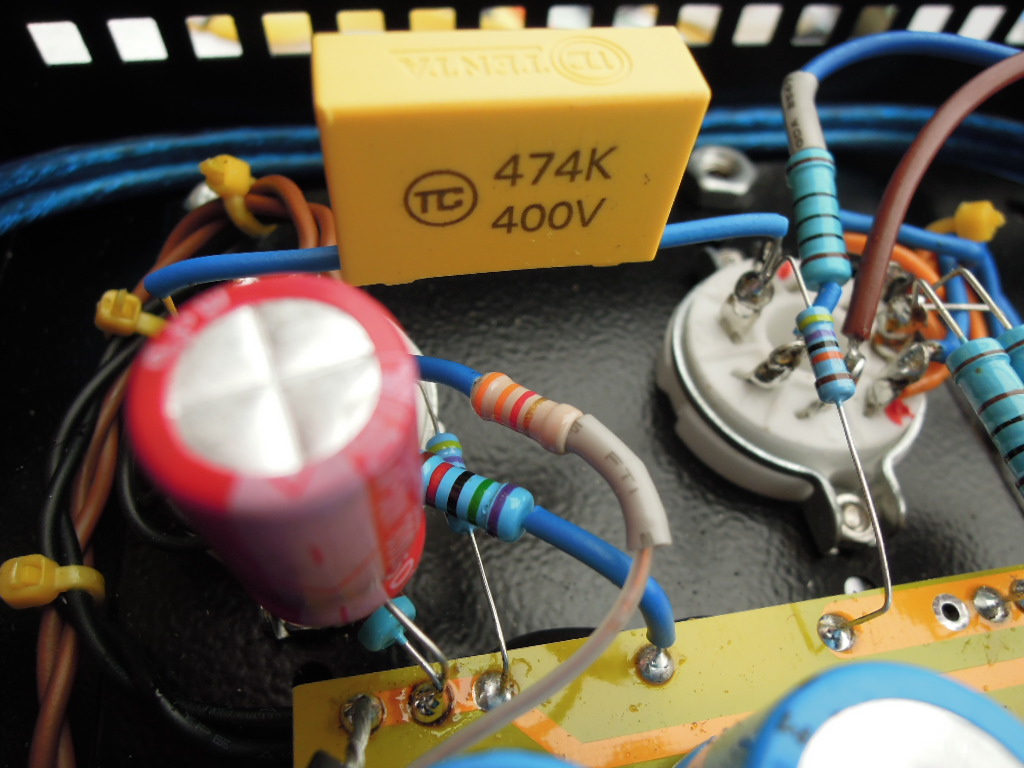
- I also replaced the EL34 cathode decoupling capacitors 220μF by 470μF,
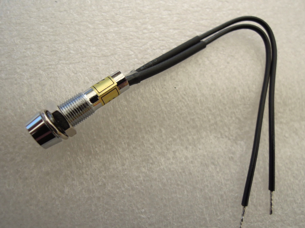
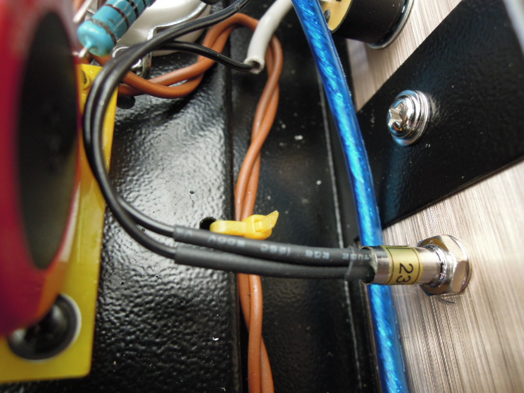
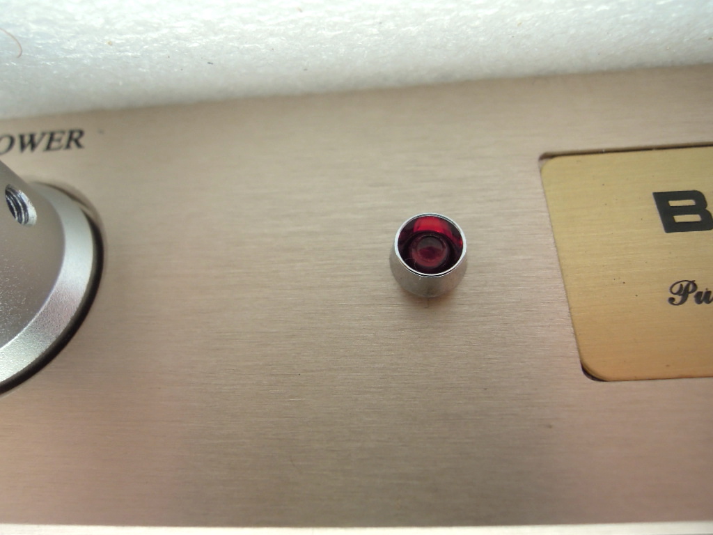
- And I installed a neon indicator light after the power switch.
So that's all for now!
Gidu
Here are my latest mods :
- I replaced the 0,22μF link capacitors by 0,47μF 400 volts MKP, and i also replaced the electrolytic capacitors that I added a few days ago, to decouple the 6N9PJ cathode resistors by high-quality 40Volts 470μF capacitor,
- I also replaced the EL34 cathode decoupling capacitors 220μF by 470μF,
- And I installed a neon indicator light after the power switch.
So that's all for now!
Gidu
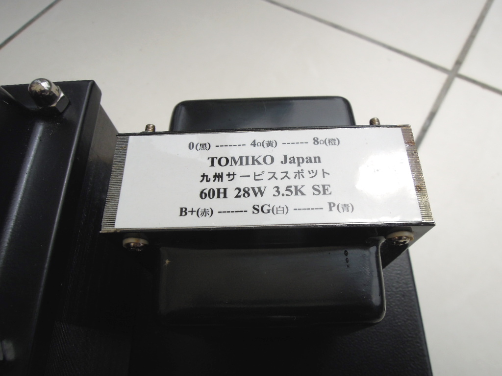
But, i shall replace the output transformers soon ! That's my next mod ...
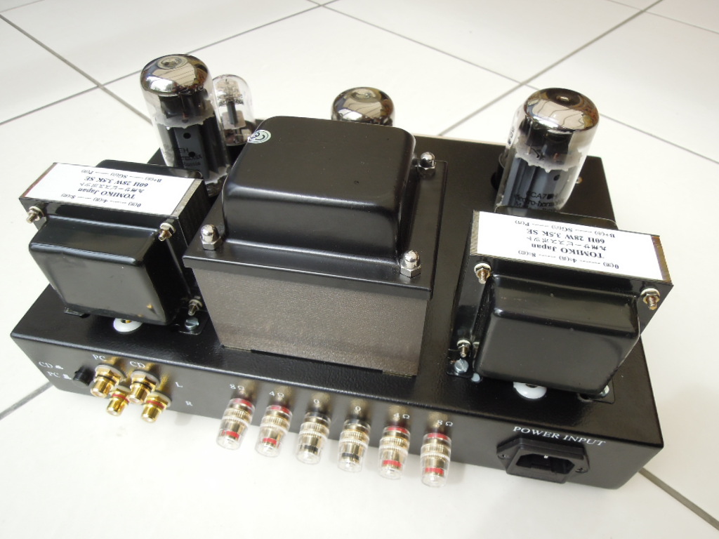
Here is the model that i bought : it's a Tomiko
M42E0g~~60_57.JPG)
And i'm waiting for the delivery ...
Gidu
Here is the model that i bought : it's a Tomiko
And i'm waiting for the delivery ...
Gidu
Last edited:
Hello !
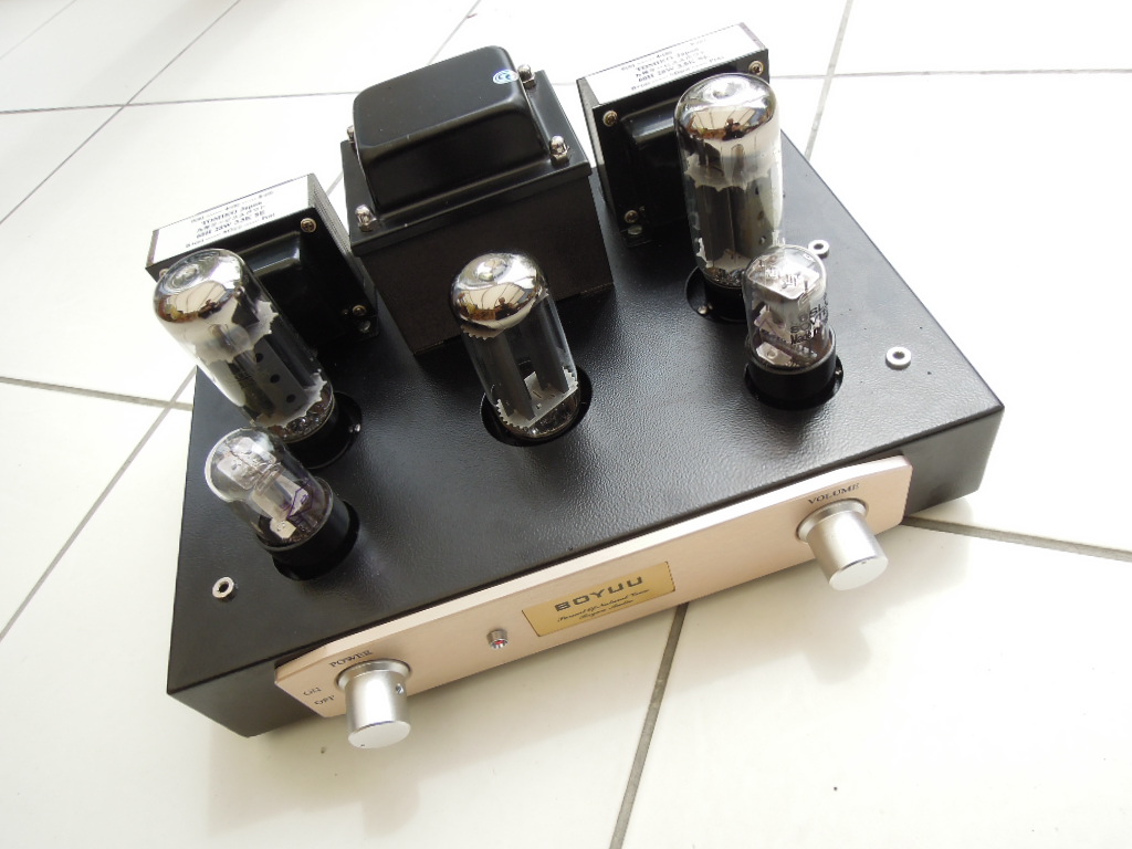
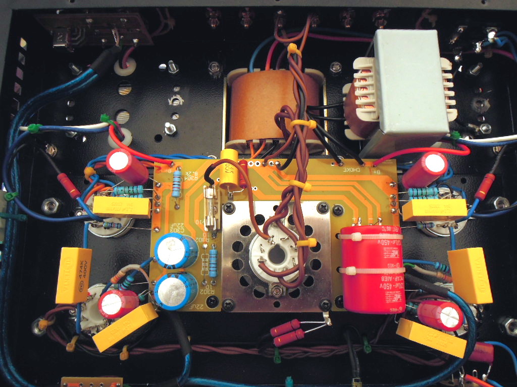
Here it is, the Tomiko output transformers are installed, it's three hours of work, but it is not too difficult, the only difficulty was to identify the color of the wires corresponding to the primary and secondary windings ...
For now, I can not really appreciate the differences in tune with the original transformers because I have a cold and I'm half deaf !
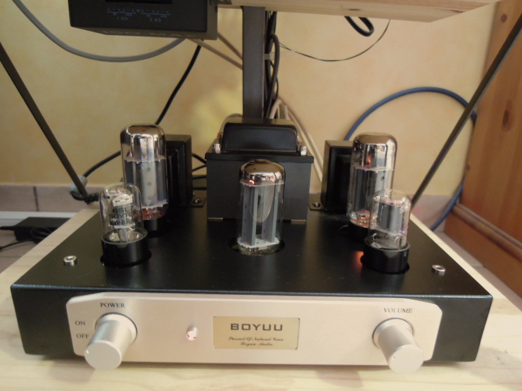
But here are some pictures of the final result:
That's all for today !
Gidu
Here it is, the Tomiko output transformers are installed, it's three hours of work, but it is not too difficult, the only difficulty was to identify the color of the wires corresponding to the primary and secondary windings ...
For now, I can not really appreciate the differences in tune with the original transformers because I have a cold and I'm half deaf !
But here are some pictures of the final result:
That's all for today !
Gidu
Hi !
My last mods :
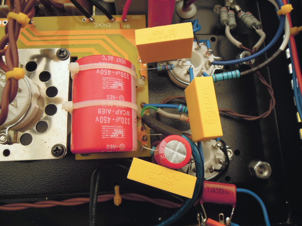
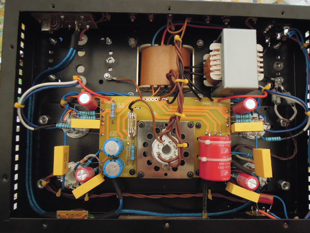
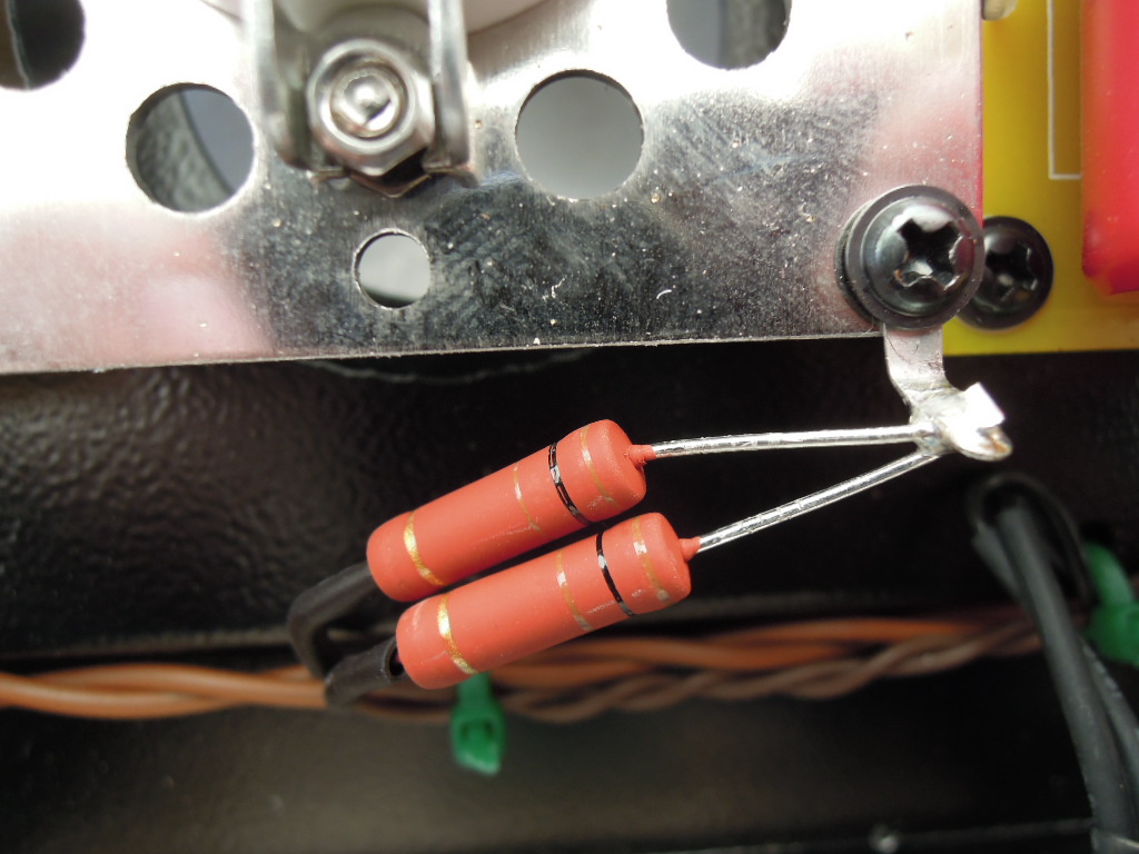
- i connected in parallel of the cathode resistors of the 6N9PJ and the EL34 2 capacitors of 2,2μF and 10nF in parallel with the existing capacitors,
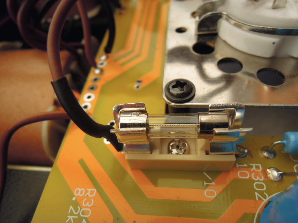
- in case of short-circuit of a capacitor, i installed a 250mA T fuse on the HT line in series with R301 to protect the power transformer and the 5Z3PJ valve.
So that's all for today !
Here are the pictures :
Gidu
My last mods :
- i connected in parallel of the cathode resistors of the 6N9PJ and the EL34 2 capacitors of 2,2μF and 10nF in parallel with the existing capacitors,
- in case of short-circuit of a capacitor, i installed a 250mA T fuse on the HT line in series with R301 to protect the power transformer and the 5Z3PJ valve.
So that's all for today !
Here are the pictures :
Gidu
Last edited:
Hi !
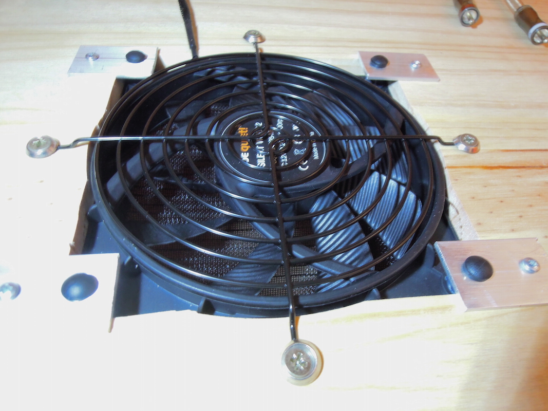
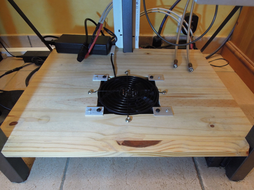
Last little DIY: the life of the components of a tube amplifier being directly related to the temperature of the components, i installed a very quiet PC fan normally operated at 12 Volts, but here under fed with 5 volts only under amplifier to cool it continuously.
After three hours of operation, the chassis and output transformers remain cold, only the power transformer is still a little warm, but far less than before !
That's all for today !
Here are some pictures :
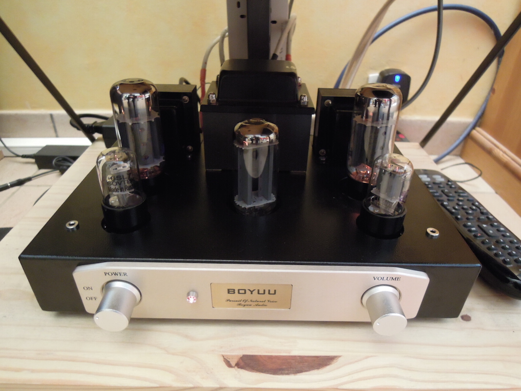
Fresh Boyuu ...
Gidu
Last little DIY: the life of the components of a tube amplifier being directly related to the temperature of the components, i installed a very quiet PC fan normally operated at 12 Volts, but here under fed with 5 volts only under amplifier to cool it continuously.
After three hours of operation, the chassis and output transformers remain cold, only the power transformer is still a little warm, but far less than before !
That's all for today !
Here are some pictures :
Fresh Boyuu ...
Gidu
Hi !
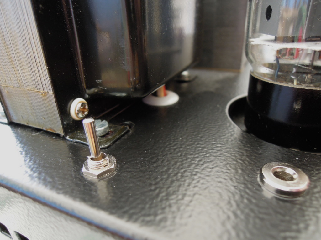
These are my last mods on this amplifier:
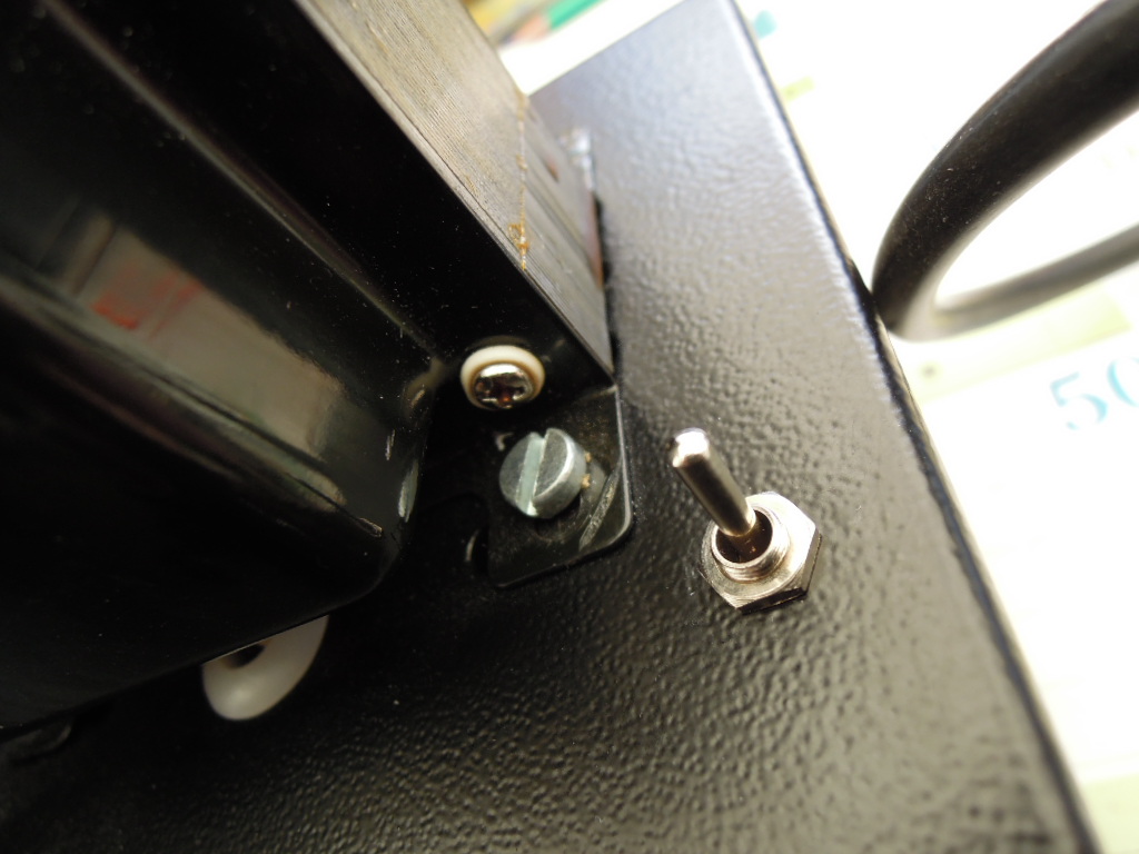
- Implementation of an Ultralinear / Pseudo triode switch,
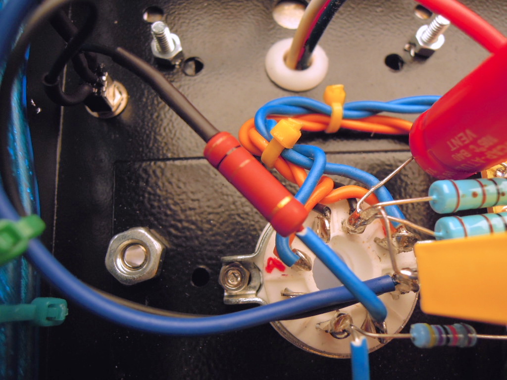
- Grounding the chassis via a 100 Ohms resistor and a 470 nanofarads capacitor parallel, instead of a simple wire,
- Changing the 100 Ohms wiring resistances of the 6,3 Volts balancing point of the 6SL7 inlet tubes.
Listening in Pseudotriode mode seems more detailed while providing more support to the lowest octaves without losing significant power.
Be careful not to switch the ultralinear Mode / Pseudo triode when the receiver is turned on (big noise in loudspeakers and switches or even EL34 may blow, so, switching is done only when the amplifier is switched off)!
That's all !
Gidu
These are my last mods on this amplifier:
- Implementation of an Ultralinear / Pseudo triode switch,
- Grounding the chassis via a 100 Ohms resistor and a 470 nanofarads capacitor parallel, instead of a simple wire,
- Changing the 100 Ohms wiring resistances of the 6,3 Volts balancing point of the 6SL7 inlet tubes.
Listening in Pseudotriode mode seems more detailed while providing more support to the lowest octaves without losing significant power.
Be careful not to switch the ultralinear Mode / Pseudo triode when the receiver is turned on (big noise in loudspeakers and switches or even EL34 may blow, so, switching is done only when the amplifier is switched off)!
That's all !
Gidu
Last edited:
hy at all...... I'm new,
i read all posts and you are incredible......
I have a question for GIDU, i'm in search of a good project, and i see all modifies that you put.....is possible post a scheme with all modifies?
Thanks
i read all posts and you are incredible......
I have a question for GIDU, i'm in search of a good project, and i see all modifies that you put.....is possible post a scheme with all modifies?
Thanks
some noob questions please regarding my first tube build
Building the 110V version: built but not yet powered
1) Before starting I powered up the OPT in isolation trying to probe the 315V leads (and others). I read 374 VAC from each lead to the center tap, double that (meter freaked and wouldn't go to 700V) across them. Expected ~315V across the two outers and half that to the center. My schematic shows 220 as the source, but assumed that they don't have separate schematic for the 110V version. Did I make a bad measurement because there was no load or current limiter?
2) My schematic had one inconsistency: 330K ohm resister from pin5 (input) of EL34 to ground on left channel, but 470K ohm on right. Looks like a revision that was half made, so I used what I had which was 330K on both.
3) Tied pin4 of 6N9PJ to pin1 as suggested by comments above (not shown on schematic)
4) Schematic shows pin "1-8" on EL34 which I assume means 1 & 8, so I tied them.
5) Planning to test with crappy 8 ohm speakers when it arrives back at my home (built it on vacation at my parents' home) Any tips about first test ( like keeping the base unscrewed in case of fire) etc.
6) Heater wiring was not shown in schematic. I wired the tubes' heaters in parallel circuits, one for each stage. (7 & 8 on 6N9PJ 2 & 7 on EL34)
An externally hosted image should be here but it was not working when we last tested it.
Building the 110V version: built but not yet powered
1) Before starting I powered up the OPT in isolation trying to probe the 315V leads (and others). I read 374 VAC from each lead to the center tap, double that (meter freaked and wouldn't go to 700V) across them. Expected ~315V across the two outers and half that to the center. My schematic shows 220 as the source, but assumed that they don't have separate schematic for the 110V version. Did I make a bad measurement because there was no load or current limiter?
2) My schematic had one inconsistency: 330K ohm resister from pin5 (input) of EL34 to ground on left channel, but 470K ohm on right. Looks like a revision that was half made, so I used what I had which was 330K on both.
3) Tied pin4 of 6N9PJ to pin1 as suggested by comments above (not shown on schematic)
4) Schematic shows pin "1-8" on EL34 which I assume means 1 & 8, so I tied them.
5) Planning to test with crappy 8 ohm speakers when it arrives back at my home (built it on vacation at my parents' home) Any tips about first test ( like keeping the base unscrewed in case of fire) etc.
6) Heater wiring was not shown in schematic. I wired the tubes' heaters in parallel circuits, one for each stage. (7 & 8 on 6N9PJ 2 & 7 on EL34)
My last mods :
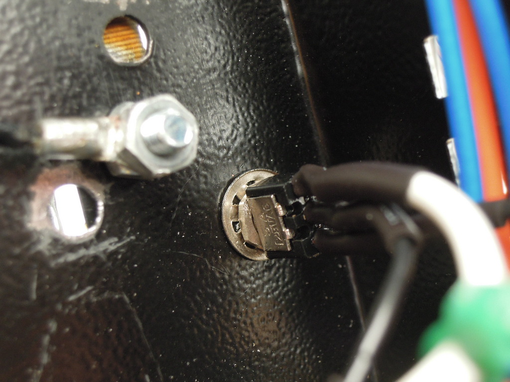
Please remove the brown capacitor across the Lorlin switch. It is a cheap part, and it is not of spec for AC 230 V .After some time it will fail to short . It is actually illegal to use in this position. You have to replace it with a X1 or X2 specification capacitor.
Need PIO capacitors
I like what you did, the accuracy and the photos.
But now you need to go with PIO capacitors !
Without pay too much you can test the Russian capacitor K75-10 PLIO (Paper Lavsan in Oil) for few bucks.
I did!
I like what you did, the accuracy and the photos.
But now you need to go with PIO capacitors !
Without pay too much you can test the Russian capacitor K75-10 PLIO (Paper Lavsan in Oil) for few bucks.
I did!
Hello!
I've just bought the A9 amp and got it today. It's not the kit but the "finished" amp.
Does the amp have autobias and how do I measure the bias?
Best regards
Stefan from Denmark
I've just bought the A9 amp and got it today. It's not the kit but the "finished" amp.
Does the amp have autobias and how do I measure the bias?
Best regards
Stefan from Denmark
Please remove the brown capacitor across the Lorlin switch. It is a cheap part, and it is not of spec for AC 230 V .After some time it will fail to short . It is actually illegal to use in this position. You have to replace it with a X1 or X2 specification capacitor.
Ok, it's a good advice, i shall replace it soon ! Tank's.
Gidu
Hello!
I've just bought the A9 amp and got it today. It's not the kit but the "finished" amp.
Does the amp have autobias and how do I measure the bias?
Best regards
Stefan from Denmark
Hi, what's the hum level on a "finished" amp like yours?
Best regards
Per, also from Denmark
Very interesting read! I have one question. What are your recommendations for better tubes then the stock tubes this amp comes with?
Hi. Just found your thread. I am building this amp (not sure of version) and everything looks like your photos but no documentation came with my kit - not even a schematic. Would you have any of the documentation that I could use? Especially the color codes of the transformer wiring? I'm pretty experienced so I can work out most of the details but I'm not certain about how the grounding should go.
Samebody tried a mu-follower or SRPP configuration?
I think is more lineal. Very easy to build.
Can achive low source impedance to drive the EL34.
Better Miller effect (Only one triode)
Cheers
I think is more lineal. Very easy to build.
Can achive low source impedance to drive the EL34.
Better Miller effect (Only one triode)
Cheers
- Home
- Amplifiers
- Tubes / Valves
- Boyuu EL34 A9 Tube Amp