How much anode power give yours Boyuu amplis?
My ampli only achive 14w (per EL34) of the posible 25W.
The rk (500 ohms) have 24v .... 48mA for 293v tube voltage !!!!
Is a limit because the OPT is very small and can´t drive more power?
Cheers
My ampli only achive 14w (per EL34) of the posible 25W.
The rk (500 ohms) have 24v .... 48mA for 293v tube voltage !!!!
Is a limit because the OPT is very small and can´t drive more power?
Cheers
I tried a SRPP mod and it works fine.Flat .
I used a 6n2p-ev, but the original driver tube is enough.
Cheers
I used a 6n2p-ev, but the original driver tube is enough.
Cheers
Hi guys, thanks to all the wonderful posts I was able to complete my first amp. I turn it on and no fires or smoke. however I have a loud buzz which begins about 15 seconds after power up. it gets louder when volume is turned up but the tone does not change.
Played some music and the lower tones, like bass are excellent but the high notes and vocals are very quiet, almost absent. Prior to power up I went through the wiring several times and after I listened to it I opened up the amp and rechecked again. All seems to be as the schematic. Only difference is they sent me 2x 330K and 2x 470K resistors instead of 4x 470K as the schematics state. Someone else posted that they used it in place of the 470K resistor that is connected to pin#5 on the EL34 so I did the same. Everything else is as per schematic.
Kinda bummed out. I was looking forward to some good music over the weekend. Oh and BTW the amp is connected to a pair of 8 ohm Energy Connoisseur C3 speakers.
Any help would be appreciated.
Hi !
To cancel the buzz, look her : http://www.diyaudio.com/forums/tubes-valves/268969-boyuu-el34-a9-tube-amp-12.html
Gidu
To cancel the buzz, look her : http://www.diyaudio.com/forums/tubes-valves/268969-boyuu-el34-a9-tube-amp-12.html
Gidu
Recent changes:
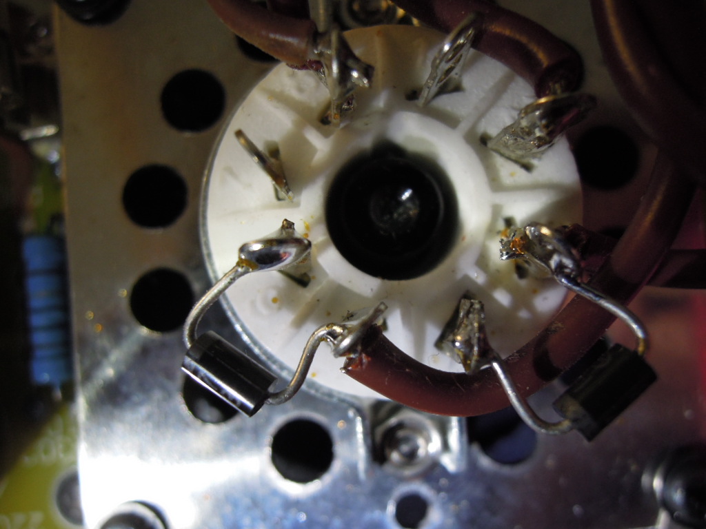
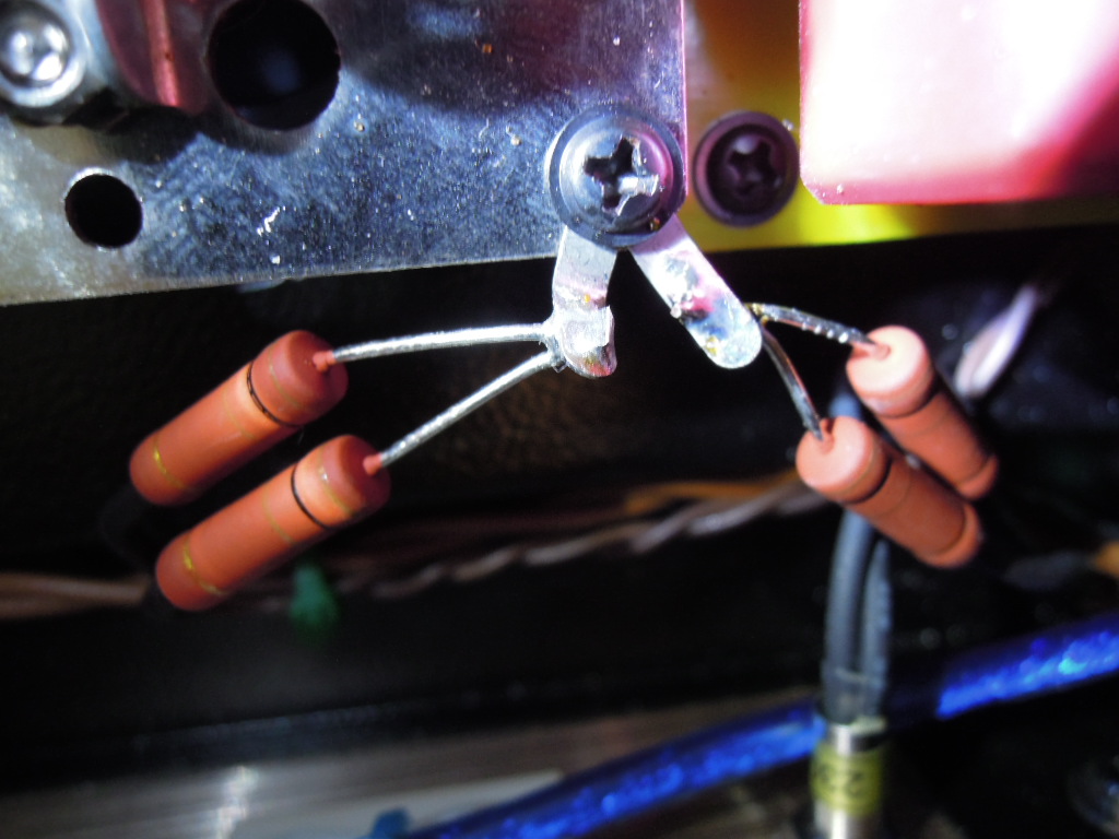
- I have added two diodes in series with the valve to protect the amp and the HP in case of failure of it, (see here : https://robrobinette.com/5e3_Modifications.htm#Backup_Diodes)
https://robrobinette.com/images/Guitar/5E3P_Build/Rectifire_Diodes.jpg
- rectified the balancing resistors of 6,3 Volts (buzz),
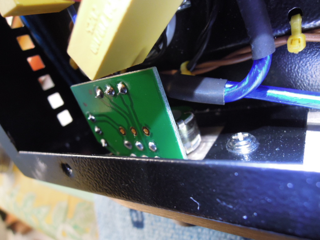
- and changed the basic potentiometer for a potentiometer with switched resistors of much better quality.
And I also changed my Electro-Harmonics 6CA7 for JJ KT77 !
That's all !
Gidu
- I have added two diodes in series with the valve to protect the amp and the HP in case of failure of it, (see here : https://robrobinette.com/5e3_Modifications.htm#Backup_Diodes)
https://robrobinette.com/images/Guitar/5E3P_Build/Rectifire_Diodes.jpg
- rectified the balancing resistors of 6,3 Volts (buzz),
- and changed the basic potentiometer for a potentiometer with switched resistors of much better quality.
And I also changed my Electro-Harmonics 6CA7 for JJ KT77 !
That's all !
Gidu
Last edited:
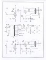
I have an A10 amplifier, which I'm really happy with... The circuit diagram is no different to the one published near the beginning of this thread.
Mine was fully-built with the quality being very good - just one dodgy solder joint now repaired. i have replaced the stock 6N2P with 6N2P-EV and it came with Shuguang EL34-B as standard.
Would it be a good idea to replace the 5Z3PJ with a GZ34 for less voltage drop and sag?
Mine was fully-built with the quality being very good - just one dodgy solder joint now repaired. i have replaced the stock 6N2P with 6N2P-EV and it came with Shuguang EL34-B as standard.
Would it be a good idea to replace the 5Z3PJ with a GZ34 for less voltage drop and sag?
Attachments
Last edited:
I use This ampli with a 6n2p-ev as SRPP configuration.
It works fine.
Netx...I will try the mu-follower.
Cheers
It works fine.
Netx...I will try the mu-follower.
Cheers
Hello Ygg-it!
Congratulations on your new site! It is very clear and didactic with nice photos!
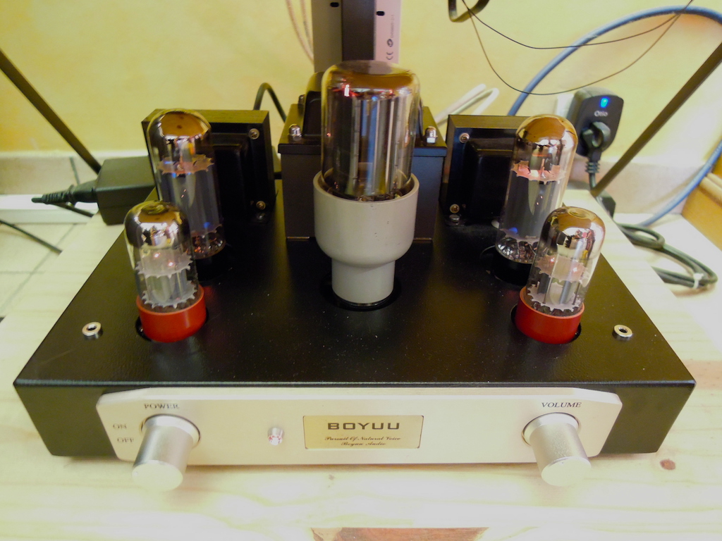
The volume potentiometer that I replaced is 50k Ohms instead of 100k originally, but now I have to turn the volume knob to 2/3 of its rotational stroke instead of the previous one third for the same sensation of sound volume. Have you noticed the same thing on your amplifier ?
Gidu
Congratulations on your new site! It is very clear and didactic with nice photos!
The volume potentiometer that I replaced is 50k Ohms instead of 100k originally, but now I have to turn the volume knob to 2/3 of its rotational stroke instead of the previous one third for the same sensation of sound volume. Have you noticed the same thing on your amplifier ?
Gidu
Hello Mission720!
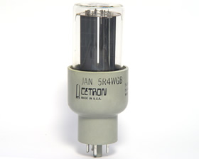
On my Boyuu A9, I replaced the rectifier valve 5Z2PJ with a JAN-5R4WGB. It is a NOS tube still very easy to find and inexpensive and its lifespan is exeptional (more than 7500 hours).
The power tubes are JJ KT77 which I am very satisfied with the musicality (they are better than the 6CA7 EH and especially than the chinese EL34 ...).
Gidu
Hello Ygg-it!
The volume potentiometer that I replaced is 50k Ohms instead of 100k originally, but now I have to turn the volume knob to 2/3 of its rotational stroke instead of the previous one third for the same sensation of sound volume. Have you noticed the same thing on your amplifier ?
Gidu
I answer to myself :
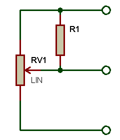
I put a resistor of 12k between the slider and the hot spot of the potentiometer to "flatten" the logarithmic response of this one and thus retrieve a volume potentiometer with a roughly usable.
Here is the pot : http://www.audiophonics.fr/fr/composants-electronique-potentiometre-commute/potentiometre-commute-stereo-anti-pop-resistances-1-cms-50k-axe-crante-p-5520.html
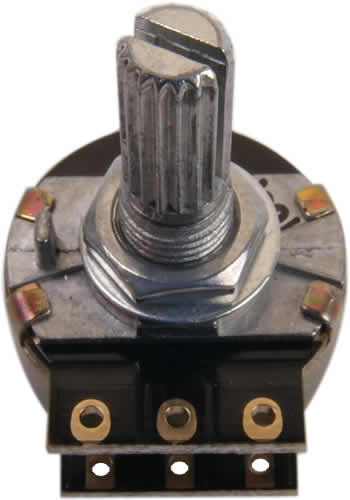
The PCB : http://www.audiophonics.fr/fr/composants-electronique-potentiometre-commute/pcb-pour-potentiometres-raccordement-entreessorties-p-8525.html
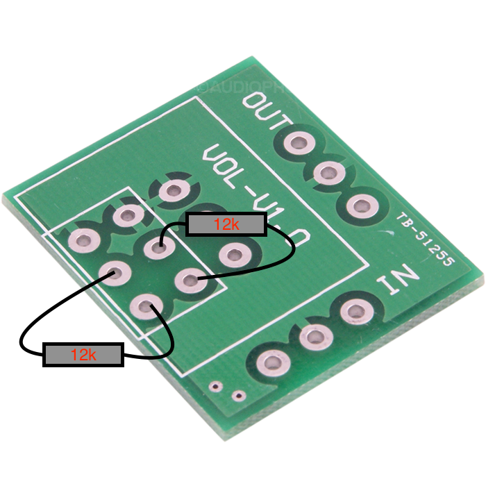
And the mod :
Take a look here (in french, sorry ...) : https://www.sonelec-musique.com/electronique_theorie_potentiometre_modif_courbe.html
The disadvantage is that the potentiometer then has an impedance seen from the source which is no longer quite constant, but in practice, it is absolutely not audible ...
Gidu
Last edited:
Hello Ygg-it!
Congratulations on your new site! It is very clear and didactic with nice photos!
The volume potentiometer that I replaced is 50k Ohms instead of 100k originally, but now I have to turn the volume knob to 2/3 of its rotational stroke instead of the previous one third for the same sensation of sound volume. Have you noticed the same thing on your amplifier ?
Gidu
Hello, a potentiometer is simply a voltage divider, so the ratio of the turns should be equal in 10K, 50K, 100K cases (I've tested the 3 and I chose the 50K the same!): at 2/3, if you have 1V at the input you should have 0.6667V at the output in each of the 3 above cases.
Unless you have in your scheme a resistor across the wiper and another lug, or you have mounted it wrongly or you have switched between a log component to a linear one, assuming that the input impedence of the tube is >> of the potentiometer one.
Yes, I know that a potentiometer behaves like a voltage divider and that the ratio at the same cursor position should be the same, but I believe that this CMS resistance potentiometer must have a more pronounced logarithmic variation profile (more dug ...). Hence the installation of these two resistances of 12k between the cursor and the input to slightly modify the logarithmic profile of this potentiometer and find a stroke a bit more usable ...
On the other hand, the PCB I used is so simple, that it is impossible to make a connection error!
On the other hand, the PCB I used is so simple, that it is impossible to make a connection error!
Tube rolling ...
This is what I observed (and listen !) regarding the various models of rectifier valves that I was able to test on my amplifier Boyuu A9, in descending order of preference regarding sound quality :
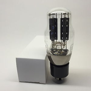
- first, the 5R4WGB JAN (Cetron): the bandwidth is balanced, the sound stage, very wide,
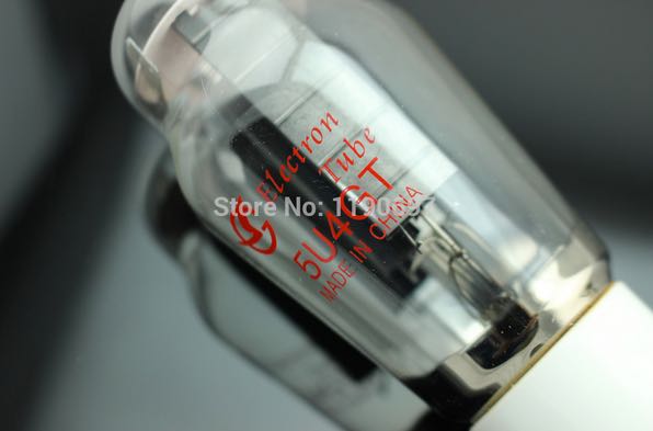
- in second place, the Chinese 5U4GT, fairly balanced on most criteria,
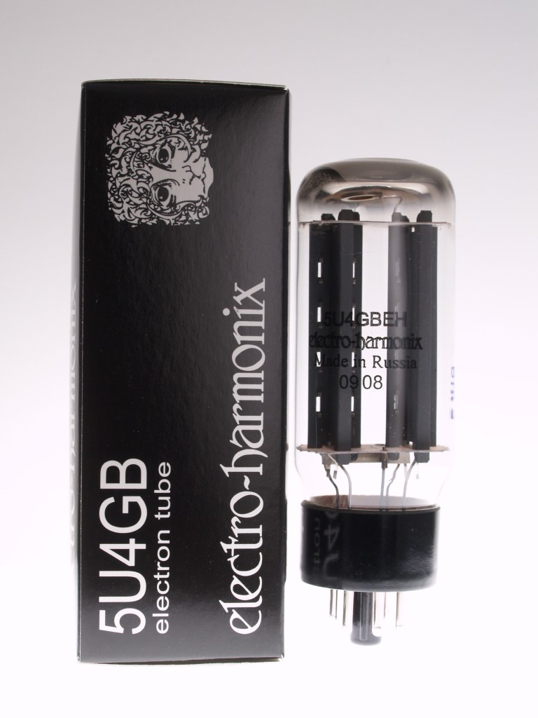
- in third place, the 5U4GB from Electro-Harmonix, correct but lacking life, relief,
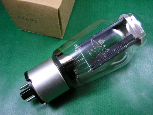
- then the 5Z3PJ delivered with the kit, very close to the 5U4GB EH,
- and finally, the 5U4G Winged "C" whose sound scene appeared to me narrow and the frequencies lowered attenuated.
In conclusion, the only rectifier valve that I keep on my amplifier Boyuu A9 is obviously the 5R4WGB. It is a JAN tube easy to find and not too expensive and whose reliability is exellent (expected lifetime: about 7500 hours).
I think that the differences observed in listening between these tubes is also probably due to the different values of the operating points, because the potential of the HT varies as a function of the tube used. The datasheets of these different tubes also show different current values, which can also affect.
What is curious is that on my amp, it is the 5R4WGB which gives the best results and it is also the one whose internal resistance is the highest and therefore the value of the B + the lowest ...
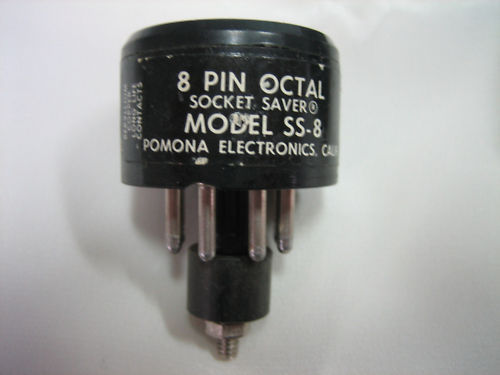
However, in order to allow this tube to be properly cooled, I have inserted a tube saver between the support of the tube and the tube itself.
Gidu
This is what I observed (and listen !) regarding the various models of rectifier valves that I was able to test on my amplifier Boyuu A9, in descending order of preference regarding sound quality :
- first, the 5R4WGB JAN (Cetron): the bandwidth is balanced, the sound stage, very wide,
- in second place, the Chinese 5U4GT, fairly balanced on most criteria,
- in third place, the 5U4GB from Electro-Harmonix, correct but lacking life, relief,
- then the 5Z3PJ delivered with the kit, very close to the 5U4GB EH,
- and finally, the 5U4G Winged "C" whose sound scene appeared to me narrow and the frequencies lowered attenuated.
In conclusion, the only rectifier valve that I keep on my amplifier Boyuu A9 is obviously the 5R4WGB. It is a JAN tube easy to find and not too expensive and whose reliability is exellent (expected lifetime: about 7500 hours).
I think that the differences observed in listening between these tubes is also probably due to the different values of the operating points, because the potential of the HT varies as a function of the tube used. The datasheets of these different tubes also show different current values, which can also affect.
What is curious is that on my amp, it is the 5R4WGB which gives the best results and it is also the one whose internal resistance is the highest and therefore the value of the B + the lowest ...
However, in order to allow this tube to be properly cooled, I have inserted a tube saver between the support of the tube and the tube itself.
Gidu
Last edited:
Hi !
You can see here a chart showing the specifications and drop voltages for some 5 volt rectifier tubes : Rectifier Tube Voltage Drop Chart - 300guitars.com or here : http://www.fourwater.com/files/fullrect.txt
I did not measure it myself, but I will do it next time !
On my amp, it is by changing the rectifier tube that the changes in the sound are most noticeable, even more than changing the power tubes, for example ...
Happy New Year !
Gidu
Last edited:
Would it be a good idea to replace the 5Z3PJ with a GZ34 for less voltage drop and sag?
On my Oldchen amplifier (same schematic as yours) I replaced the 5Z3P with a GZ34 Philips/Mullard with copper plate edge, and it sounds slightly better. The b+ is now almost 20v higher. My GZ34 is a pull from a discarded power supply I got in the '80 so it is a "free" upgrade; the current price of a NOS GZ34 of this kind is insane and is not worth the money on this application, at least to me. On a SE amplifier the current draw is almost constant so the internal resistence of the rectifier plays a minor role compared to push-pull.
Comparing the schematic of my amp to yours, on my amplifier there is an extra 10k resistor from b+ to pin 4 (g2) of the EL34, and the cathode resistor has a much lower value (cathode voltage at idle is 19v).
I'm unsure why the manufacturer added this additional path to the g2, in parallel with the ultralinear tap of the output transformer. May it be a shourtcut to use a cheaper transformer? I'm tempted to remove it.
Comparing the schematic of my amp to yours, on my amplifier there is an extra 10k resistor from b+ to pin 4 (g2) of the EL34
It's strange, I've never seen it on this kind of schema on a single-ended amp. It looks like a hybrid operation between the Ultra Linear and the Pseudo-Triode ...
Gidu
This is the first time I see this arrangement. I saw this resistor from b+ to g2 in parallel to the UL OPT tap on a design fitted with a pentode/triode switch: the resistors insure a bias to the screens during the time the contact is switching. But on my Oldchen EL34 amplifier there is no switch and the resistor has a fairly large value (10k). Maybe the purpose is to smooth transformer resonance, but a RC network would be a better choice. I've been unable to find an explanation. It may simply be a error or arbitrary modification as often found on China-sourced amplifier.
I checked my notes about the 5Z3P to GZ34 tube swap. The B+ was 310V with 5Z3P, it is 340v with the GZ34. A side note: is there a standard way to test the emission of the rectifier tube and compare it to the emission of a new tube, to get a emission performance espressed in % relative to a new tube? When I restore a radio, I replace the rectifier when the voltage drop is obviously excessive (substantial ripple and low b+), or if the power transformer is mechanically buzzing (this means that a diode failed or it is significantly weaker than the other), or if the filament is open. It seems that either the rectifier tube works fine or it is defective, with no gray zone in between. I've less experience on rectifier tubes in Hi-Fi amplifier. May a weakened emission from a old tube be a issue, or does the tube fails sharply?
I checked my notes about the 5Z3P to GZ34 tube swap. The B+ was 310V with 5Z3P, it is 340v with the GZ34. A side note: is there a standard way to test the emission of the rectifier tube and compare it to the emission of a new tube, to get a emission performance espressed in % relative to a new tube? When I restore a radio, I replace the rectifier when the voltage drop is obviously excessive (substantial ripple and low b+), or if the power transformer is mechanically buzzing (this means that a diode failed or it is significantly weaker than the other), or if the filament is open. It seems that either the rectifier tube works fine or it is defective, with no gray zone in between. I've less experience on rectifier tubes in Hi-Fi amplifier. May a weakened emission from a old tube be a issue, or does the tube fails sharply?
The sound of rectifier ...
Take a look here about the sound of rectifier : The Sound of Rectifier - Tube Maze
Gidu
Take a look here about the sound of rectifier : The Sound of Rectifier - Tube Maze
Gidu
- Home
- Amplifiers
- Tubes / Valves
- Boyuu EL34 A9 Tube Amp