Hello Alchemist11 - firstly thanks for sharing your Boyuu A9 kit building experience... there are many who will be helped by this to take the plunge 🙂
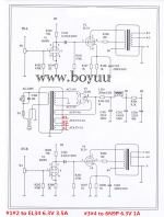
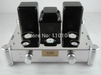
So, I "cheated" and bought a pre-assembled unit and asked for the circuit diagram (which I posted in this thread earlier) and which is labelled as A10, which uses 6N2P-EV used for first stage amplification rather than 6N9PJ so is not the same but uses similar build and power supply and power stages with EL-34b.
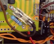
It's good you have uploaded photos. After looking at them I might make a suggestions to re-visit a number of the solder joints and re-flow. I can't know what type of solder, what soldering iron or temperature you're using but from the photos there appear to be some 'dry joints'. I have taken a snip from one of your uploads and circled in red what looks to be a solder-defficient joint and in blue where maybe the solder hasn't flowed (insufficient temperature, lack of flux).
As such, these can be a source of hum, localised overheating and general poor performance as additional resistance and/or capacitance has been introduced.
For voltages measured, with no load they will be higher than expected. The voltage rating on the capacitors is their maximum working voltage, and this has no effect on the circuit they are used in, save if too low they will blow (sometimes with a bang!). Under normal operating conditions I would expect the measured voltage for the completed circuit to be steady.
A modern multi-meter has a high input resistance and so offers practically no load to the circuit, measuring an 'open loop' output voltage (i.e. one without feedback regulating the output) will typically show a much higher voltage.
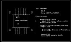
To check the output from your rectifier valve it would be sensible to use a dummy load if you think there may be a problem. At 12.5W per channel, 25W total class A with efficiency of 25% then consumption at B+ voltage should be around 100W. The rated unit power consumption is 230W. The stated transformer output is 315v which gives about 220v dc for B1 so be very careful.
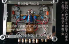
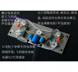
Attached also are some pictures of point-to-point wired A10 from their advert - this might help you.
So, I "cheated" and bought a pre-assembled unit and asked for the circuit diagram (which I posted in this thread earlier) and which is labelled as A10, which uses 6N2P-EV used for first stage amplification rather than 6N9PJ so is not the same but uses similar build and power supply and power stages with EL-34b.
It's good you have uploaded photos. After looking at them I might make a suggestions to re-visit a number of the solder joints and re-flow. I can't know what type of solder, what soldering iron or temperature you're using but from the photos there appear to be some 'dry joints'. I have taken a snip from one of your uploads and circled in red what looks to be a solder-defficient joint and in blue where maybe the solder hasn't flowed (insufficient temperature, lack of flux).
As such, these can be a source of hum, localised overheating and general poor performance as additional resistance and/or capacitance has been introduced.
For voltages measured, with no load they will be higher than expected. The voltage rating on the capacitors is their maximum working voltage, and this has no effect on the circuit they are used in, save if too low they will blow (sometimes with a bang!). Under normal operating conditions I would expect the measured voltage for the completed circuit to be steady.
A modern multi-meter has a high input resistance and so offers practically no load to the circuit, measuring an 'open loop' output voltage (i.e. one without feedback regulating the output) will typically show a much higher voltage.
To check the output from your rectifier valve it would be sensible to use a dummy load if you think there may be a problem. At 12.5W per channel, 25W total class A with efficiency of 25% then consumption at B+ voltage should be around 100W. The rated unit power consumption is 230W. The stated transformer output is 315v which gives about 220v dc for B1 so be very careful.
Attached also are some pictures of point-to-point wired A10 from their advert - this might help you.
Attachments
Hello Mission720,
Thanks for your post and I hope your A10 is giving you hours of joy.
Yes I am aware that some of my soldering is not quite up to standar. It's been a long time since I done any electrical work. I had to change the EL34 Cathode Resistors because they had burnt out, and it's not always easy to de-solder and re-solder but i am sure I will improve with practice. I will recheck my soldering, thanks...🙂.
The rectifier appears be OK, I was surprised that my voltage reading was higher than expected, when I measured on an open circuit with no load.
Thankyou,
Tim.
You also have a potential problem on this filtering capacitor: there is a drop of solder that can cause a short circuit between the B + (the HT) and the ground ...
Look at this photo, at the end of the red arrow :
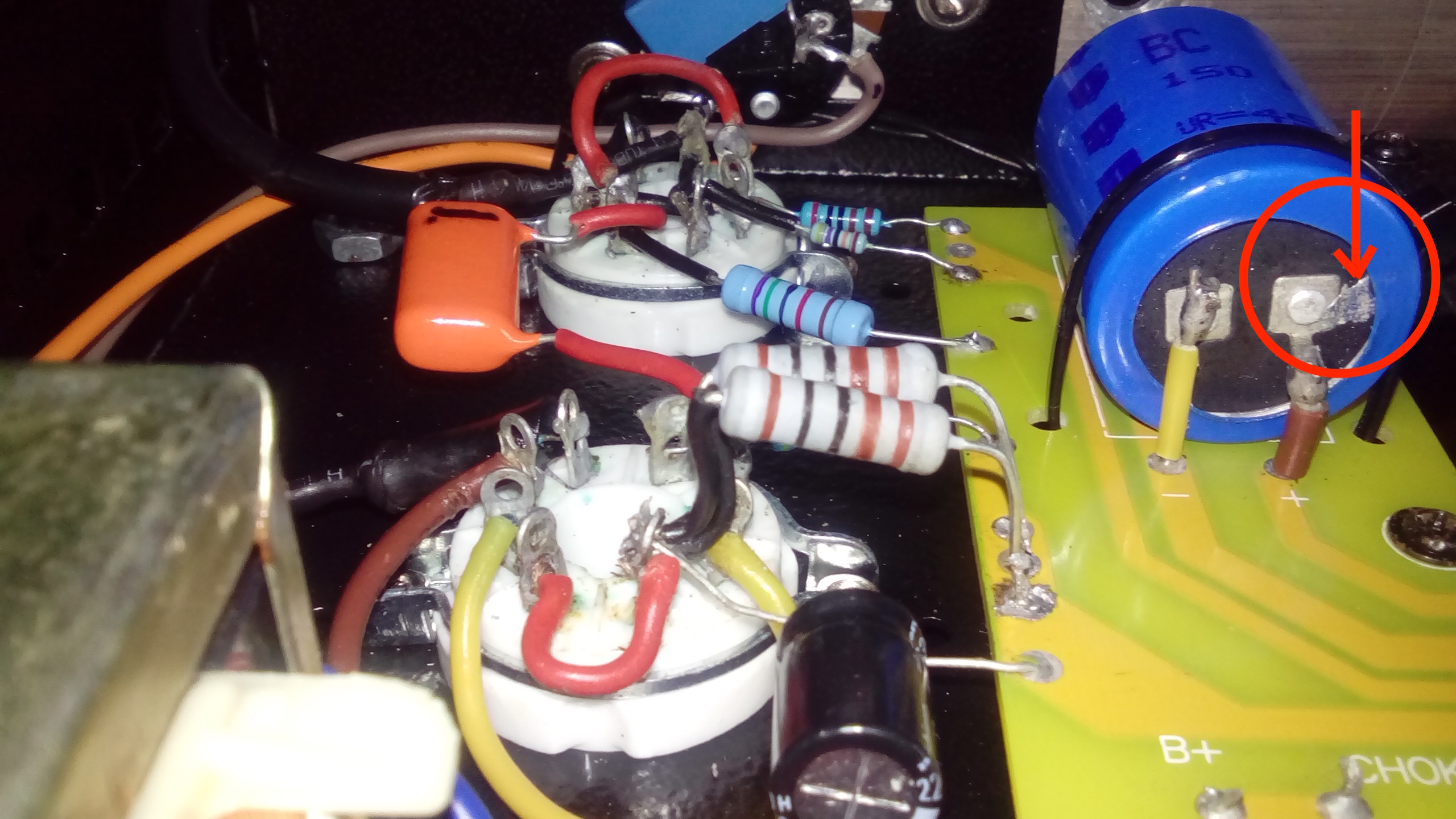
But in general, it is absolutely necessary to improve the quality of your welds, because most of those that can be seen in the photos are bad. This may be due to poor quality welding flux or an unsuitable soldering iron!
Finally, check and re-check your wiring because the schematic is good.
Good luck !
Look at this photo, at the end of the red arrow :
But in general, it is absolutely necessary to improve the quality of your welds, because most of those that can be seen in the photos are bad. This may be due to poor quality welding flux or an unsuitable soldering iron!
Finally, check and re-check your wiring because the schematic is good.
Good luck !
Alchemist11 - are you using separate flux and non-flux solder? I ask this as there seems to be a lot of waxy residue around your solder joints.
I would really recommend you invest in self-fluxing solder, such as 20.601.01037 | Felder Lottechnik 1mm Wire Lead Solder, +183 → +190C Melting Point, 40% Lead, 60% Tin, 100g | Felder Lottechnik
I am very pleased with the A10 version, which uses 6N2P-EV and EL34b valves, same rectifier. The 6N2P-EV I use have replaced the original Chinese, the EL34b are Shuguang matched pair, the original we Shuguang anyway.
Any queries, please do ask!
Look at this photo, at the end of the red arrow :
That photo link will not open for me.
Can you attach the picture to the message instead, please?
It's good you have uploaded photos. After looking at them I might make a suggestions to re-visit a number of the solder joints and re-flow. I can't know what type of solder, what soldering iron or temperature you're using but from the photos there appear to be some 'dry joints'. I have taken a snip from one of your uploads and circled in red what looks to be a solder-defficient joint and in blue where maybe the solder hasn't flowed (insufficient temperature, lack of flux).
Yes I am aware that some of my soldering is not quite up to standard.
But in general, it is absolutely necessary to improve the quality of your welds, because most of those that can be seen in the photos are bad. This may be due to poor quality welding flux or an unsuitable soldering iron!
I agree that the solder joints could be improved. The unseen bottom side of the board could provide more information- good flow on the 'work/solder side' of the board doesn't always result in a good looking joint on the upper (component) side. It takes practice.
What soldering iron/soldering station are you using? Also, what size tip are you using on your iron? Any good brand of 60/40 type (Pb containing) rosin core solder should do a good job with the right iron, tip and heat setting.
Hello guy's,
Thanks for the great response that I had so far, but not very promising as I expected. II'm obviuosly not very good at soldering, and this is just a start for me.
I am using A Hakko 550D soldering iron with a small flat tip, and leaded 60/40 solder wire about 2mm diameter, with separate flux paste. The temp is set between 350 - 400 c.
The problem is'me regardless of my confidence in soldering, I don't have the steadiest of hands, and a year of health problems which causes me to continuously shake and jitter, my disability can sometimes get in the way when trying to achieve something, frustrating but that life...
Anyway, I tried to re-solder and quess what ? my soldering iron packed-up, so i pulled out my spare one which is 40 watts not sure what make but has a very large tip. Then more disaster stroked, I went a bit far and burnt one of the contacts on the PCB where you connect the output transformer to B+. So not a very good day today.
I wait for a better day !!!
Last edited:
Sorry to hear about you misadventure alchemist. There are multiple other spots on the board which have B+. It will just require a longer run. Hope you feel better. Keep us posted.
Keep at it alchemist, the solder doesn't have to be pretty. I haven't any to hand for measuring but 2mm sounds quite heavy. You may do well to invest in some possibly lighter gauge good quality solder such as WBT 0800 silver solder which I swear by.
Doesn't matter if it's silver or not but I think a lighter gauge would help.
Meanwhile keep at it man! I take my hat off to you for getting stuck in to such a project. There's nothing like getting it done and having a cuppa while listening.
Just be careful. It's not just electricity you have to watch for either. A few weeks back I developed a nasty habit of laying my iron on the bench rather than placing it in its stand. This was fine until I picked it up by the wrong end.
Last edited:
Alchemist:
I use Kester '44' solder which is 0.8mm (.030") diameter. Thicker solder is OK for working on tube gear without PC boards, but the 0.8mm stuff works for pretty much everything I do (which doesn't include surface mount device soldering).
BTW, the Kester '44' (also available online in the UK from the same source as the WBT 0800, and probably from any good electronics supply place) is relatively inexpensive. (UK 20 p per m).
If you don't have them already, a couple of other 'essentials' (for me) are a solder sucker and solder wick. A flux pen is also handy sometimes.
Hello guy's,
I repaired electronics for a major power company here in Canada for 30 years.Had a company from the states called Pace send a specialist to give soldering courses to all the technicians. Main points were use 63/37 solder (it is eutectic same melt and freeze temp),ALWAYS flux your joints(even though the solder has it in its core),clean leads and pads with alcohol and lint free tissues (not erasers etc. as it leaves residue).
...I am using A Hakko 550D soldering iron with a small flat tip, and leaded 60/40 solder wire about 2mm diameter, with separate flux paste. The temp is set between 350 - 400 c.
Sorry to hear about your health problems - I find it bad enough trying to solder with two steady hands as I find it necessary to use a decent magnifying glass for small PCB work, like helping my son with building a Nixie Tube clock kit...
For me, that's where using self-fluxing solder helps. Some 40-odd years ago I was struggling with a small reel of what must have been plumbers solder at ~5mm and a tin of flux paste, again which I think must have been plumbers to go with the thick solder. My dad encouraged me to clean components by dipping in hydrochloric acid...
One further thought I had, and that is if you are using imported or NOS components, such as capacitors, resistors, it's probably worth cleaning up the leads, maybe with a quick couple of wipes using wire wool but nothing too abrasive: Often resistors will have glue residue from bandoliers or will have partially oxidised. Either of those will hamper ensuring a good solder joint.
Hello Guys,
Thanks, so much for encouraging me too keep at it, I know you all trying to help and cheers for that. 🙂
I will get ligher guage solder wire and I won't be using my spare soldering iron becuase the tip too big for this project. Whether I can get this Hakko 550D working again which I don't 'think so' I would have to break the bank for a new one, I bought this from EBay last year, and no guarantee, so that did'nt last very long.
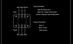
I have managed to fix the broken B+ PCB connection that I accidently burnt out. I put one end of a short wire to the PCB choke connection that already links to B+ as a bypass, and the other end to the Red wire of the output trandformer togetther with the Black wire on the choke. So, in theory I just pick up the B+ Power line from a different connection on the same track, if that makes any sense... ??? 😕
Thanks again... I keep you posted.
Thanks, so much for encouraging me too keep at it, I know you all trying to help and cheers for that. 🙂
I will get ligher guage solder wire and I won't be using my spare soldering iron becuase the tip too big for this project. Whether I can get this Hakko 550D working again which I don't 'think so' I would have to break the bank for a new one, I bought this from EBay last year, and no guarantee, so that did'nt last very long.
I have managed to fix the broken B+ PCB connection that I accidently burnt out. I put one end of a short wire to the PCB choke connection that already links to B+ as a bypass, and the other end to the Red wire of the output trandformer togetther with the Black wire on the choke. So, in theory I just pick up the B+ Power line from a different connection on the same track, if that makes any sense... ??? 😕
Thanks again... I keep you posted.
I don't know the Hakko 550D - do you have a picture to post? Parts (including cheap knockoffs) are available for the Hakko irons, usually...so repairs are usually possible.Whether I can get this Hakko 550D working again which I don't 'think so' I would have to break the bank for a new one, I bought this from EBay last year, and no guarantee, so that did'nt last very long.
Thanks again... I keep you posted.
I have a Hakko 936 which I like- it's been replaced now in the retail market by the Hakko fx-888. A friend bought one of those and likes it, though the appearance makes it look like a toy.
On a whim, I bought a cheap Chinese knockoff of the 936 to "see how bad it was", and I've been using it for the past couple of years - though I don't spend more than a couple of hours a week on average with the iron powered up. The knockoff works fine - I keep a larger tip in it and a smaller tip in the real Hakko and use them both.
PM me if you want more info on the knockoff- I can find it here somewhere....
Hi VicoriaGuy,
Sorry, I had mistaked that I had the 550D, I have the Hakko FX-888D. I don't know why I thought I had 550D silly me. I should have gone to 'Specsavers....'.
Sorry, I had mistaked that I had the 550D, I have the Hakko FX-888D. I don't know why I thought I had 550D silly me. I should have gone to 'Specsavers....'.
I have managed to fix the broken B+ PCB connection that I accidently burnt out.
Have you any way of posting a picture of this?
Wow just figured out my hum problem. My amp sits about a foot away from a wall dimmer. on a wooden table. Just realized I get the hum every time the light on the dimmer is turned on. Don't know whether it's the physical proximity or that the outlet I'm plugged into is on the same circuit? (too tired to figure it out now) It's strange that the hum is only on one channel and volume dependent. I'm still going to switch the internal signal cables to shielded ones and modify the input area with new connectors and switch. At least for now I can listen to music without that annoying hum.
BTW I got my matched pair Electro Harmonix EL34 tubes. Somewhat lower gain, different tone. I'll have to play around with different tube combinations to hit the sweet spot. Waiting on some caps I ordered to swap out the coupling caps.
BTW I got my matched pair Electro Harmonix EL34 tubes. Somewhat lower gain, different tone. I'll have to play around with different tube combinations to hit the sweet spot. Waiting on some caps I ordered to swap out the coupling caps.
- Home
- Amplifiers
- Tubes / Valves
- Boyuu EL34 A9 Tube Amp