Hello Pcan / Gidu,
Firstly, keep up the great work with your experimentation and reporting.
I have a factory built A10 Boyuu EL34 SE amp and I'm very pleased with it. I have changed the original Chinese 6N2P pre-amp valves with matched pair 6N2P-EV Russian 'military' valves. Can't say I have noticed a great deal of difference, however it was more of a purchase for longevity.
Although my set came with Shuguang EL34-B already, I also bought a matched pair of Shuguang EL34-B: Using a bias measuring meter they indicate 51 to 53mA when warm - how does this compare with others experience?
I'm still using the original 5Z3P rectifier valve and so was thinking about changing it to a GZ34 which has a much less volatge drop. I know this will increase B+ however I haven't measured the existing B+. Local supply voltage (UK) is about 230vac.
Would you expect other modification considerations if a GZ34 is used?
Hello.
From my own experience, I am not sure that increasing the value of B+ results in a gain in sound quality ! In any case, on my Boyuu A9 it is the tube that has the biggest voltage drop that gives the best sound quality ... the 5R4WGB JAN (Cetron). And the loss of power is absolutely insignificant!
As far as the power tube, among those I tried, (EL34 Shuguang, EL34 EH, 6CA7 EH and KT77 JJ), it is the KT77 JJ which gave the best results on all levels ...
Gidu
Hi Gidu - thanks for the feedback....
Given that I have the A10 version (not sure how different from A9 it is!!) and that I'm measuring 51-53mA bias, is tube rolling to KT77 just a straight swap or should I expect to make other component changes?
Given that I have the A10 version (not sure how different from A9 it is!!) and that I'm measuring 51-53mA bias, is tube rolling to KT77 just a straight swap or should I expect to make other component changes?
Hi !
Tube rolling to KT77 just a straight swap ! Nothing to modify ... The diagram of this amplifier is in automatic polarization thanks to the resistance (300 to 500 Ohms) of cathode of the EL34.
Look here : The Last Word On Biasing
I quote :
Gidu
Tube rolling to KT77 just a straight swap ! Nothing to modify ... The diagram of this amplifier is in automatic polarization thanks to the resistance (300 to 500 Ohms) of cathode of the EL34.
Look here : The Last Word On Biasing
I quote :
The cathode biasing method is self-regulating, to an extent, because increases in cathode current create a larger voltage drop across the cathode resistor, which in turn, creates a larger negative grid-to-cathode voltage, which counteracts the increase in current. The tube will reach a stable point of equilibrium and stay there.
Gidu
Ah... so the 500 Ohms made by 2 x 1k in parallel makes it perform in cathode biasing. In some example circuits I see a capacitor bypass for the cathode baising resistor to get rid of any AC, so good to see it in the A10 circuit...
At 51-53mA though does this bias the EL34 in the middle of the linear part of the operating curve?
I might well see if I can get some KT77s, although tyhe 'kinkless' bit is not really applicable in single-ended application...
At 51-53mA though does this bias the EL34 in the middle of the linear part of the operating curve?
I might well see if I can get some KT77s, although tyhe 'kinkless' bit is not really applicable in single-ended application...
The "kink" is caused when the plate voltage swings significantly below the screen voltage.
That can happen in Push Pull, and it can happen in Single Ended.
It can happen in Pentode mode, and it can sometimes happen in Ultra Linear mode.
It all depends on the tube type, and how far the plate voltage swings below the screen voltage.
It can Not happen when the Pentode or Beam Power tube is Triode Wired (at least it will not happen unless you use an unusually large resistance to connect from the plate to the screen; but then that is not really Triode wiring it). I bet that a 100 Ohm resistor from plate to screen would not be a problem, but a 10k Ohm resistor would probably be a problem.
If you look at the tube curve graphs of some types of "Kinkless" tubes that are in Pentode/Beam Power connection mode, you can still sometimes still see small(er) kinks.
Although my set came with Shuguang EL34-B already, I also bought a matched pair of Shuguang EL34-B: Using a bias measuring meter they indicate 51 to 53mA when warm - how does this compare with others experience?
Would you expect other modification considerations if a GZ34 is used?
I measured 70mA on my amplifier. I changed the cathode resistor, the value is now 270 ohm. I replaced the stock Shuguang EL34-B with two used Philips EL34 from the '60. I got them for free because the getter on one of them is almost completely gone but it works well. They are matched far better than the Shuguang.
To preserve the life of the GZ34 I lowered the first two filter capacitors to 33uF each from the factory 100uF+100uF and I installed a T315mA fuse on pin 2, before the first capacitor.
I'll put the original Shuguang EL34-B pair back in and measure the bias again. Actually, I bought a set of quad matched Shuguang EL-34B just in case I fancied making a PP amp so I have a further two to try.
The bias measuring meter (Suzier) has 4 channels and uses piggy-back bases with flying leads and 3.5mm jack plugs on the end of the live feed from the pigg-back base (This will mean the exposed jack metal connectors are live of course, however low the voltage/current is...). When the channel selector for each bias source is switched only that channel has a signal path. This was quite a surprise when I found I could only listen to left or right on my amp.
I presume this is because an extra resistor (say 1 ohm) is introduced into the bias circuit via the valve base adaptor and the voltage is measured across that resistor to determine the current, however there is a single resistor in the meter rather than individual resistors in each base?
Hi !
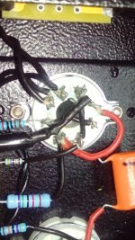
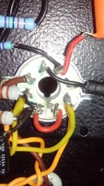
And finally, a last small mod of my Boyuu A9 ... or rather a small repair !
Indeed, the PC/CD switch had, for some time, false intermittent contacts.
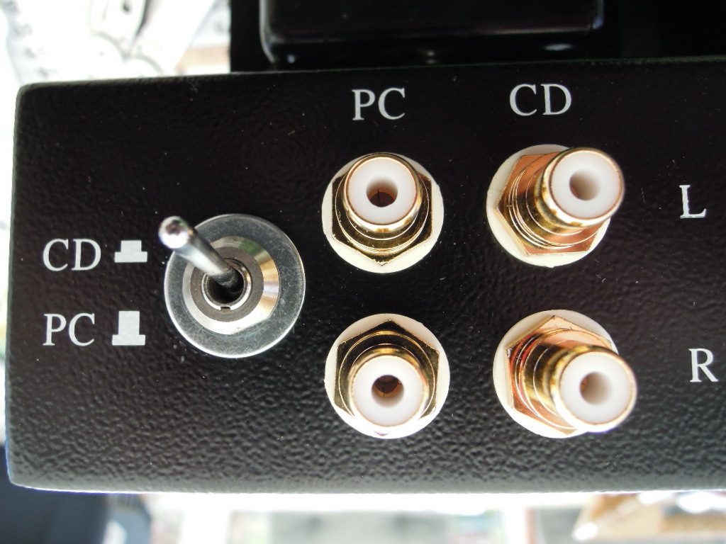
So I decided to replace it with a good quality dual miniature inverter and i took the opportunity to also replace the very average quality RCA input sockets (they were already oxidized !) by good new sockets.
That's all for today !
Gidu
And finally, a last small mod of my Boyuu A9 ... or rather a small repair !
Indeed, the PC/CD switch had, for some time, false intermittent contacts.
So I decided to replace it with a good quality dual miniature inverter and i took the opportunity to also replace the very average quality RCA input sockets (they were already oxidized !) by good new sockets.
An externally hosted image should be here but it was not working when we last tested it.
An externally hosted image should be here but it was not working when we last tested it.
That's all for today !
Gidu
Last edited:
Hi guys, I have the same amp and thanks to the very helpful posts, was able to complete it. I even made some of the mods that are described here. The amp sounds great and I'm very happy with it. The only problem I have is a persistent hum from the left channel. It is present about 15 seconds after power up. The volume of the hum increases when I increase the volume of the amp. The hum increases in volume until about 90% open. Then it suddenly disappears. So with volume maxed, there is no hum. I have tried swapping tubes and no change. The hum is present with no source plugged in. I tried to move the wires away from sources of noise but no change.
Any help is appreciated.
Any help is appreciated.
Hello 🙂
I am just starting out on valve amps and I know more or less the very basis of how value amps works, and still learning. I am new to this forum and it’s my first post on the forum and I hope some are able to help.
I decided to invest in a project to keep me occupied and to simulate my brain, and have a bit of fun bringing valve amps back to this reality.
I did a little shopping on EBay and see quite a few people bought the Boyuu Chinese Valve kits, so I went for the boyuu A9.
When the kit arrived it did not have a schematic or any documentation, I emailed the EBay seller and they sent me some photos and a schematic that didn’t quite match the contents of the kit.
The kit came with a black 39 Ohms Wire Wound Resistor presuming it replaces the three 10 ohms 301/303 resistors, and instead of 4 x 470K as shown in the diagram, I got 2 x 470K and 2 x 330K. Looking at the diagram the 470’s go from pin 1 of the 6N9PJ tube to ground, and the 330’s go from pin 5 of the EL34 to ground at a guess.
It looks like the documents has not been updated with regards to the contents, I also noticed the PCB had a label saying ‘A9-POWER/2’ printed on the top right corner above the 22 uF Cap, could the ‘/2’ be referred to a later revision ?
I am aware that some people have done some upgrades to their amps which I would like to do eventually, but it’s all too much to take in ‘now’ First thing is to get this amp up and running as it is and eliminate the problems have the moment.
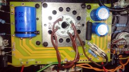
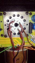
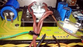
I built the amp according to the given schematic, photos of the transformer wiring and a picture of the complete build. Some ’quality’ pictures of point-to-point wirings WOULD be very useful!! On the 6N9PJ I linked Pins 1-4, 3-6 and 2-5, and on the EL34 Pins 1-8
When I powered ON with everything connected, there was some popping and sparking that looked like it was coming from the rectifier tube for a few seconds then a loud hum and some smoke appearing minutes later. I Powered OFF and turned over the unit, 4 of the 1K Resistors connected from pin 8 of EL34 to ground had turned black, and the line fuse did not blow.
When I replaced the 1K resistors with the same wattage ‘2W’, I took some readings from the transformer high voltage secondary that goes to pins 4 and 6 of the rectifier, and it reads 342 VAC on each pin, should it be 315 VAC like on the schematic. My mains is UK 240 VAC, but the diagram states 220 VAC as the supply voltage.
Then i measured the rectifier cathode (output) pin 8 and it read 458 VDC !!! why? Where did that 116 VDC come from when I should get 342 VDC if the primary winging is getting 240VAC in ?
Have I got the wrong transformer for 240 VAC inlet voltage?, it seems that the winging ratio is incorrect for 240 - 315 VAC. Is my rectifier defected, because of the high 458 VDC when you would expect 342 VDC based on transformer’s winging ratio. What going on here… 😡
Is there a way to verify weather my rectifier has had it? Was the popping and sparking an indication to why I was getting such high DC Voltage? If need to replace the rectifier, what would you recommend for a substitute?
I apologise for the lengthy post, as this is my first post and I’m hoping my future posts won’t be as long as this, now that I’ve fully explained things. Can you guys help?
Thanks in advance,
Tim.
I am just starting out on valve amps and I know more or less the very basis of how value amps works, and still learning. I am new to this forum and it’s my first post on the forum and I hope some are able to help.
I decided to invest in a project to keep me occupied and to simulate my brain, and have a bit of fun bringing valve amps back to this reality.
I did a little shopping on EBay and see quite a few people bought the Boyuu Chinese Valve kits, so I went for the boyuu A9.
When the kit arrived it did not have a schematic or any documentation, I emailed the EBay seller and they sent me some photos and a schematic that didn’t quite match the contents of the kit.
The kit came with a black 39 Ohms Wire Wound Resistor presuming it replaces the three 10 ohms 301/303 resistors, and instead of 4 x 470K as shown in the diagram, I got 2 x 470K and 2 x 330K. Looking at the diagram the 470’s go from pin 1 of the 6N9PJ tube to ground, and the 330’s go from pin 5 of the EL34 to ground at a guess.
It looks like the documents has not been updated with regards to the contents, I also noticed the PCB had a label saying ‘A9-POWER/2’ printed on the top right corner above the 22 uF Cap, could the ‘/2’ be referred to a later revision ?
I am aware that some people have done some upgrades to their amps which I would like to do eventually, but it’s all too much to take in ‘now’ First thing is to get this amp up and running as it is and eliminate the problems have the moment.
I built the amp according to the given schematic, photos of the transformer wiring and a picture of the complete build. Some ’quality’ pictures of point-to-point wirings WOULD be very useful!! On the 6N9PJ I linked Pins 1-4, 3-6 and 2-5, and on the EL34 Pins 1-8
When I powered ON with everything connected, there was some popping and sparking that looked like it was coming from the rectifier tube for a few seconds then a loud hum and some smoke appearing minutes later. I Powered OFF and turned over the unit, 4 of the 1K Resistors connected from pin 8 of EL34 to ground had turned black, and the line fuse did not blow.
When I replaced the 1K resistors with the same wattage ‘2W’, I took some readings from the transformer high voltage secondary that goes to pins 4 and 6 of the rectifier, and it reads 342 VAC on each pin, should it be 315 VAC like on the schematic. My mains is UK 240 VAC, but the diagram states 220 VAC as the supply voltage.
Then i measured the rectifier cathode (output) pin 8 and it read 458 VDC !!! why? Where did that 116 VDC come from when I should get 342 VDC if the primary winging is getting 240VAC in ?
Have I got the wrong transformer for 240 VAC inlet voltage?, it seems that the winging ratio is incorrect for 240 - 315 VAC. Is my rectifier defected, because of the high 458 VDC when you would expect 342 VDC based on transformer’s winging ratio. What going on here… 😡
Is there a way to verify weather my rectifier has had it? Was the popping and sparking an indication to why I was getting such high DC Voltage? If need to replace the rectifier, what would you recommend for a substitute?
I apologise for the lengthy post, as this is my first post and I’m hoping my future posts won’t be as long as this, now that I’ve fully explained things. Can you guys help?
Thanks in advance,
Tim.
edit from last post
I mean Primary and Secendary "Windings"... not winging.. just to correct my spelling, sorry about that 😀
Tim.
I mean Primary and Secendary "Windings"... not winging.. just to correct my spelling, sorry about that 😀
Tim.
Hi alchemist, I must have had the same version as yours. Mine came with the single wire wound resistor and 330k instead of the 470k. I bought a pair of 470k resistors and replaced the 330k ones. I find that I had better gain with the 470k. (I had used the 330k for both pre amp and power tubes just to experiment)
As for the smoke, the 1K resistors that turned black were on both channels or just one side? Those are the cathode resistors that are connected to the ground for the EL 34 tube. Is everything grounded properly, or rather is anything grounded that should not be grounded? I would double and triple check the wiring against the schematic. Use a highlighter to trace each connection. Sounds like you have a short.
If you can post pictures of your wiring.
Hi cman008,
Thanks for the reply. I will replace the two 330k to 470k. The 1k cathode resistors that turned black were on both channels. I will thoroughly check everything against the schematic, unfortunately I dont have a highlighter or a camara.
Thanks for the reply. I will replace the two 330k to 470k. The 1k cathode resistors that turned black were on both channels. I will thoroughly check everything against the schematic, unfortunately I dont have a highlighter or a camara.
To cman008:
Sorry for the late response ...
Have you solved your persistent hum problem on a single channel ? Otherwise, depending on what you describe, I think this hum can only come from a wiring problem upstream of the volume potentiometer or the potentiometer itself !
This problem may also be due to the poor quality of the CD/PC switch, which is why I replaced the small printed circuit, the 4 RCA sockets and the switch on my amp ...
This can also be a problem of mass discontinuity between the volume potentiometer and the input RCA sockets.
All this is to be checked with a universal controller, taking the usual precautions, because HT is lethal ...
Gidu
Last edited:
Hi alchemist11 !
To help you, it would be very useful to see your wiring. You do not have a smartphone with a camera? Maybe you can get some one ...
Gidu
Hi cman008,
Thanks for the reply. I will replace the two 330k to 470k. The 1k cathode resistors that turned black were on both channels. I will thoroughly check everything against the schematic, unfortunately I dont have a highlighter or a camara.
To help you, it would be very useful to see your wiring. You do not have a smartphone with a camera? Maybe you can get some one ...
Gidu
Can you guys help?
Thanks in advance,
Tim.
Tim:
Folks here are generally very helpful and you should be able to get your problem solved, eventually. A lot of us have built those Chinese amp kits, in one form or another.
First, as Gidu has said, you need to figure out a way to get some pictures uploaded here. If that involves buying a small digital camera, it will be part of the cost of your electronics hobby.
Also, posting the schematic you are working with, will help as well.
Do you have any spare parts (resistors, tubes, etc.) or do you just have what came with the kit?
Do you have a 'dim bulb tester'? You should make one for yourself if you don't.
For a starter I don't think that the 220-240 volt difference is causing the (dramatic) symptoms you describe. It's more likely that you have a wiring error - either what most of us have done, making a wrong connection, or there's an error in the schematic (less likely but it sometimes happens).
Thanks Gidu, not solved yet, but I think it is the small circuit board where the inputs are connected. I saw your mod and like it a lot. I will be making the same change myself. I ordered some shielded wire so I'm waiting for it to arrive before I do the mod. I'm also thinking of adding a switch for altering the bias on the power tubes. I already have the triode/UL switch. I actually prefer the triode mode. I'll post pictures as soon as I finish.
Alchemist. I think you have a short. With no power connected you can try to check for shorts with your ohm meter. Hope you figure it out. Keep us posted.
Alchemist. I think you have a short. With no power connected you can try to check for shorts with your ohm meter. Hope you figure it out. Keep us posted.
To cman008 :
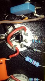
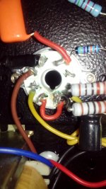
Depending on the switch you have purchased, you will need to use two washers of a suitable diameter to compensate for the diameter of the chassis hole that is too large for a miniature switch. These washers are visible in my photos. And it is very difficult to desolder the original RCA sockets without damaging them: you will also have to change them ...
Gidu
Last edited:
Hi Folks,
Thanks for all your replies. I have managed to get hold of a camera at last.
I think I made a mistake when I took the last measurements . At the time I only had the rectifier plugged in and no other tubes connected, I did this see why the 1k resistors had burnt out in the first place, to protect my other tubes in case the voltages were too high and to verify if the Rectifier is working correctly. I
forgot that the capacitors were charging up and of course the caps are rated to 450V and no current draw, therefore the current had no way to go ‘dead-end’. I think it explains why the voltages just kept rising until the caps reached it capacity. So that said, the transformer and rectifier is working probably.
My readings now are; 680VAC Full wave, so that 340 VAC on rectifier pin 4 & 6, 340 VDC output from rectifier because I am on 240VAC supply. The schematic states 220 V as supply, is the 20 V difference going to make an effect on the overall performance?
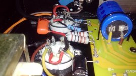
I have added a 250mA fuse from the rectifier’s output to the 39 ohms resistor thanks to Gidu, and a 10k as a grid stopper just after the volume control. I have also put two 470k instead of the 330k that came with the kit, the amp has four 470k like in the schematic below.
I don’t have any spare parts only a handful of resistors and, not sure any of them are going to be suitable.
Thanks for all your replies. I have managed to get hold of a camera at last.
I think I made a mistake when I took the last measurements . At the time I only had the rectifier plugged in and no other tubes connected, I did this see why the 1k resistors had burnt out in the first place, to protect my other tubes in case the voltages were too high and to verify if the Rectifier is working correctly. I
forgot that the capacitors were charging up and of course the caps are rated to 450V and no current draw, therefore the current had no way to go ‘dead-end’. I think it explains why the voltages just kept rising until the caps reached it capacity. So that said, the transformer and rectifier is working probably.
My readings now are; 680VAC Full wave, so that 340 VAC on rectifier pin 4 & 6, 340 VDC output from rectifier because I am on 240VAC supply. The schematic states 220 V as supply, is the 20 V difference going to make an effect on the overall performance?
I have added a 250mA fuse from the rectifier’s output to the 39 ohms resistor thanks to Gidu, and a 10k as a grid stopper just after the volume control. I have also put two 470k instead of the 330k that came with the kit, the amp has four 470k like in the schematic below.
I don’t have any spare parts only a handful of resistors and, not sure any of them are going to be suitable.
Attachments

- Home
- Amplifiers
- Tubes / Valves
- Boyuu EL34 A9 Tube Amp