Close up
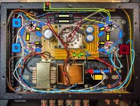
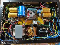
Here's A close-up of my build and how it's comparing to my previously posted design. This was before I noticed the shorting OPTs and began taking it apart again. Notice how i implemented the voltage/potential divider by using a 5 lug terminal tag strip board and securing it with one of the OPT cover fixing screws. The device also doubles as a bleeder with an LED pilot light.
Over to the right, the Ultralinear/Triode switch is visible - its very simple, really.
The screentap from an OPT feeds into the top lug. Out of the middle lug comes the wire that feeds into the screen via a 100R resistor. Into the bottom feeds a direct shunt from the Anode. The switch has 3 gangs but i only used two for left and right. So throwing the switch one way connects the screentap to the screen via the 100R resistor and the other way connects the shunt from the anode to the screen via the same resistor. Simples. I had it connected properly the first time around and there's no reason for the OPTs to have been damaged by this mod.
Attachments
Last edited:
Hi Tubby23,
I would be a bit concerned about this high B+ voltage. I would assume the solid state rectifier (if you are using it ) will give you higher voltage, and normally about 325v (B+) using tube rectifier (325v is higher than others , because I am in Australia and we have 240volt AC)
I would doubt the missing of output transformer could ever cause this high voltage. the transformer and EL34 will consume 15 watt in the way how it biased now. It will not be able to drop that much voltage if you put them back online. This is just my thoughts.
Daniel
Hi mate.
Both OPTs along with their tubes are offline.
Would that be less concerning?
Genuine question as I haven't any specs at hand regarding the OPTs and mine are shorted so..
Both OPTs along with their tubes are offline.
Would that be less concerning?
Genuine question as I haven't any specs at hand regarding the OPTs and mine are shorted so..
Hi Tubby23 ,
I have some resistance information for the output transformer that I measured before I built the amp:
the primary: Red-Brown 205 Ohm, secondary: Red-Blue 0.3 ohm/2.72mh, Blue-Black 0.7 ohm /3.22mh
my power transformer output 337v without any load, 325v with everything powered.
For the high B+ of 390 volt, I would be a bit worried about the filter caps, some of these only marked as 400 volt. And you will need to increase the R103/203 for 6N9P to lower the plate voltage for that stage.
high B+ probably will not harm too much to EL34, in your case , you will almost have a plate voltage about 375 volt, and about 60mA plate current, your Amp will be biased at 90% max dissipation ,which is recommended for class A. You will have very warm sound, unfortunately my Amp only biased at 60%, too hard to achieve 90%
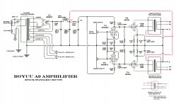
A9 Schematic - Corrected
Thanks for your observation. I have corrected that missed point and other points raised by others and attach my latest schematic.
The lower 6N9P should be rotated 180 degrees (to being upside-down).
Pins 2 and 5 are the plates; pins 3 and 6 are the cathodes.
Thanks for your observation. I have corrected that missed point and other points raised by others and attach my latest schematic.
Attachments

Hi Tubby23 ,
I have some resistance information for the output transformer that I measured before I built the amp:
the primary: Red-Brown 205 Ohm, secondary: Red-Blue 0.3 ohm/2.72mh, Blue-Black 0.7 ohm /3.22mh
my power transformer output 337v without any load, 325v with everything powered.
For the high B+ of 390 volt, I would be a bit worried about the filter caps, some of these only marked as 400 volt. And you will need to increase the R103/203 for 6N9P to lower the plate voltage for that stage.
high B+ probably will not harm too much to EL34, in your case , you will almost have a plate voltage about 375 volt, and about 60mA plate current, your Amp will be biased at 90% max dissipation ,which is recommended for class A. You will have very warm sound, unfortunately my Amp only biased at 60%, too hard to achieve 90%
Hi Daniellu.
I got it working!
Turns out I had swapped the OPTs primary red and blue wires around! LOL. My bad for not measuring their resistance before.
But I assumed that the thicker wires were the outputs...
For the primaries I got 208R between red and brown. 111R between brown and blue. 97R between blue and red.
The secondaries were 0.8R red/black. 0.4 blue/black.
With everything connected, B+ is 336V and my potential divider for the elevated heater voltage is putting out 45V as I designed.
It's all working great now!
Got it working!
I assumed that the thicker opt wires were the outputs!
Corrected that and am getting 336v on B+ and it's working grand.
The rectifier would arc for a second or so during startup but I added UF4007 diodes to its input and has stopped doing that.
Happy days!
I assumed that the thicker opt wires were the outputs!
Corrected that and am getting 336v on B+ and it's working grand.
The rectifier would arc for a second or so during startup but I added UF4007 diodes to its input and has stopped doing that.
Happy days!
Attachments

Great to hear that you found your problem and got it going. With this problem in mind I have included a note on my schematicGot it working!
I assumed that the thicker opt wires were the outputs!
Corrected that and am getting 336v on B+ and it's working grand.
The rectifier would arc for a second or so during startup but I added UF4007 diodes to its input and has stopped doing that.
Happy days!
Attachments

Got it working!
I assumed that the thicker opt wires were the outputs!
Corrected that and am getting 336v on B+ and it's working grand.
The rectifier would arc for a second or so during startup but I added UF4007 diodes to its input and has stopped doing that.
Happy days!
Thank you!
Instead of digging out my connections I simply opened up the OPTs boxes and swapped the red and blue wires around.
I feel that heavier guage wire should be on the secondary anyways as that's where there's more current.
I feel like the factory operative mis-connected my OPTs.
Great to hear that you found your problem and got it going. With this problem in mind I have included a note on my schematic
I assumed that the thicker opt wires were the outputs!
Corrected that and am getting 336v on B+ and it's working grand.
The rectifier would arc for a second or so during startup but I added UF4007 diodes to its input and has stopped doing that.
Happy days![/QUOTE]
Thank you!
Instead of digging out my connections I simply opened up the OPTs boxes and swapped the red and blue wires around.
I feel that heavier guage wire should be on the secondary anyways as that's where there's more current.
I feel like the factory operative mis-connected my OPTs.
Hi Tubby23,
That's really good news!
Yes the rectifier arc can easily fixed by UF4007, same happened to mine.
now it's time to enjoy the music.
That's really good news!
Yes the rectifier arc can easily fixed by UF4007, same happened to mine.
now it's time to enjoy the music.
Well done
Thank you!
Instead of digging out my connections I simply opened up the OPTs boxes and swapped the red and blue wires around.
I feel that heavier guage wire should be on the secondary anyways as that's where there's more current.
I feel like the factory operative mis-connected my OPTs.[/QUOTE]
Hello "Tubby23", the job you have done is really impressive. For my part, I was content to assemble the "Boyuu A9" with the components of the kit. However, I will advise you (if you haven't already done so) to change the RCA jacks because they are of poor quality. In fact they end up oxidizing. I will install these: https: //www.aliexpress.com/item/4000057620071.html? Spm = a2g0s.8937460.0.0.3bef2e0eow74XO. Best regards
I assumed that the thicker opt wires were the outputs!
Corrected that and am getting 336v on B+ and it's working grand.
The rectifier would arc for a second or so during startup but I added UF4007 diodes to its input and has stopped doing that.
Happy days!
Thank you!
Instead of digging out my connections I simply opened up the OPTs boxes and swapped the red and blue wires around.
I feel that heavier guage wire should be on the secondary anyways as that's where there's more current.
I feel like the factory operative mis-connected my OPTs.[/QUOTE]
Hello "Tubby23", the job you have done is really impressive. For my part, I was content to assemble the "Boyuu A9" with the components of the kit. However, I will advise you (if you haven't already done so) to change the RCA jacks because they are of poor quality. In fact they end up oxidizing. I will install these: https: //www.aliexpress.com/item/4000057620071.html? Spm = a2g0s.8937460.0.0.3bef2e0eow74XO. Best regards
Thank you!
Instead of digging out my connections I simply opened up the OPTs boxes and swapped the red and blue wires around.
I feel that heavier guage wire should be on the secondary anyways as that's where there's more current.
I feel like the factory operative mis-connected my OPTs.
Hello "Tubby23", the job you have done is really impressive. For my part, I was content to assemble the "Boyuu A9" with the components of the kit. However, I will advise you (if you haven't already done so) to change the RCA jacks because they are of poor quality. In fact they end up oxidizing. I will install these: https: //www.aliexpress.com/item/4000057620071.html? Spm = a2g0s.8937460.0.0.3bef2e0eow74XO. Best regards[/QUOTE]
Thank you, Learn.
I had 45 days to read this forum and Mr Valve Wizard's Valve Preamplifier book so I picked some things up, lol.
It's been a great learning experience - I had electro tech classes in high school many years ago but, apart from designing my own 12v power supply for an old car radio to use as a bedroom stereo and speakers, I've never really worked with electronics (except building computers) and much less valves/tubes! So I'm quite chuffed with myself!
Regarding the RCA jack's.. Yes I've noticed that the central pins have begun coming loose to the point of rotation of I'm not careful plugging cables in. I now regret not having used the little PCB board to wire them up. At least that would have stopped the pins rotating because they'd be solidly soldered to the board. But I hated that clicky button. Well, now that you're telling me that they're also prone to oxidation, they got to go!
Forget RCA jacks
Bypass the RCA jacks with Bluetooth. Easy to do and only costs a few bucks. RCAs can still be used for certain applications but it is so good to relax on your lounge and stream/control your music wirelessly from your iPad, phone, computer🙂 or any Bluetooth device.
Hello "Tubby23", the job you have done is really impressive. For my part, I was content to assemble the "Boyuu A9" with the components of the kit. However, I will advise you (if you haven't already done so) to change the RCA jacks because they are of poor quality. In fact they end up oxidizing. I will install these: https: //www.aliexpress.com/item/4000057620071.html? Spm = a2g0s.8937460.0.0.3bef2e0eow74XO. Best regards
Bypass the RCA jacks with Bluetooth. Easy to do and only costs a few bucks. RCAs can still be used for certain applications but it is so good to relax on your lounge and stream/control your music wirelessly from your iPad, phone, computer🙂 or any Bluetooth device.
Bypass the RCA jacks with Bluetooth. Easy to do and only costs a few bucks. RCAs can still be used for certain applications but it is so good to relax on your lounge and stream/control your music wirelessly from your iPad, phone, computer🙂 or any Bluetooth device.
I'm using a Google Chromecast music streaming connected via toslink to my DAC, feeding the amp. Lovely.
Anyone think that this is a worthwhile upgrade to our A9s?
£40.55 8%OFF | 185W amplifier set transformer, 96X60 power transformer +3.5K output transformer, suitable for electronic tube EL34 6P3P FU5 FU7
185W amplifier set transformer, 96X60 power transformer +3.5K output transformer, suitable for electronic tube EL34 6P3P FU5 FU7|Transformers| - AliExpress
£40.55 8%OFF | 185W amplifier set transformer, 96X60 power transformer +3.5K output transformer, suitable for electronic tube EL34 6P3P FU5 FU7
185W amplifier set transformer, 96X60 power transformer +3.5K output transformer, suitable for electronic tube EL34 6P3P FU5 FU7|Transformers| - AliExpress
Upgrade reply
Personally, I will recommend this instead as an improvement: (Tung-Sol EL34B Matched Pair – Thomann UK) I installed them a few weeks ago and they are better than the original tubes.
Personally, I will recommend this instead as an improvement: (Tung-Sol EL34B Matched Pair – Thomann UK) I installed them a few weeks ago and they are better than the original tubes.
Perhaps it would be enough to change the output transformers by these models which look quite good: Customized 15w Single Ended Tube Amp's Output Transformers 2 PCS for EL34 Fu50 807 KT88 Others HIFI EXQUIS|hifi exquis|tube amptube amp output transformer - AliExpress
Personally, I will recommend this instead as an improvement: (Tung-Sol EL34B Matched Pair – Thomann UK) I installed them a few weeks ago and they are better than the original tubes.
Do you know the specifications of the stock OPTs?
In particular the input impedance?
All else being the same, can I just install any el34 and not worry about changing the cathode resistor?
- Home
- Amplifiers
- Tubes / Valves
- Boyuu EL34 A9 Tube Amp