Hi Bobbie,
the feedback resistor will have about 150v voltage drop on it, it only consumes about 0.1 watt, so 0.5w or more would be OK.
I am terrible in describing personal listening experience in words. What I felt was that when I listened to the same album of Dianna Krall's , I could 'see'/hear that the singer had more space around her and I could position her better. By saying that, please don't trust anything I just said. The listening experience is so personal, I would not convince other people a better system. I completely gave it up after I watched the youtube video about Yanny and Laurel, it proved to me we actually hearing different things (and then we argued about it, why should we?), I highly recommend everyone have a quick view /listen this youtube video.
YouTube
In this video, despite all my effort wanted to hear 'Laurel', I only heard 'Yanny', my friends heard both. I am convinced that we can hear different things when we are listening.
Last edited:
I put a 220K R between EL34 anode (pin 3) and 6N9P anode (pin 2,5 before the coupling cap C102). as you said, it improves distortion. but I like it in the way that it opens up sound stage for whatever reason. I never removed this negative feedback after my experimenting.
Thank you - I've been revising "my" design as per TG's recommendations.
Getting ready to post the alterations.
I see what you did regarding your implementation of feedback - funny how FB can be easily added in various ways. I understand that the preamp stage's cathode was originally left unbypassed for this reason however I chose to increase gain and HF response by bypassing it therefore a new methode of FB was called for.
My Future Build - Revised
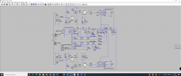
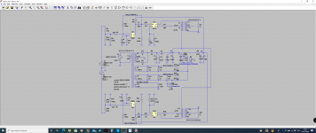
So after taking into consideration TG's comments and recommendations, here's my revised project modeled in LTspice almost in it's entirety. I still haven't received my A9 yet.
1) I'm keeping the Humpots! 😀
2) Discarded the plan of tapping into the tubes' cathodes in order to elevate the heater circuit - instead I've added a potential divider across B+ and ground, raising the heaters by about 42V. This feeds into the humpots' wiper and the ends are attached to the valves' heater pins. One pot for the preamp and one for the power tubes. In the pics attached I ran my model in spice and it shows the heaters on both the 6N9S and EL34 42V well clear of their cathode voltages while well away from the 100V Vhk maximum of the 6N9Ss.
Don't know the EL34's but I assume its probably more than that or the same at the very least. Anyways, the model's running fine.
I've included an ASC file of my model that you can run or modify in Spice to your heart's content - I did the work so you don't have to! LOL
You might have to install valve/tube models in your copy beforehand, though.
3) I've abandoned my plans on adding 10nf caps alongside the 470uf electrolytic bypass caps on cathodes.
4) Transformer HT leads will now be fused by 2A slow-blows.
5) I'll leave the 0.1uf caps on the power rail as they're easy to implement - I mean there's holes in the board especially for them and I see small caps alongside large ones on power supplies all over youtube - so it must be good! 😀
Right - that' it for now.
Apparently my A9 has passed customs and is now being shipped to the UK...so hurray!
Special thanks to the straight-talking TG for his help.
Attachments

And here's what my mods are going to look like.
Notice, I intent to install the humpots and pseudo triode/ultra linear switch into the holes reserved for the optional tube cage.
Whoops! Just noticed I painted the coupling caps on backwards!
Whilst these aren't polarized there's benefit to determining which side the outer jacket is one and placing that side on the lower impedance side - such as towards ground and as in this case, towards the anode of the proceeding stage.
Here's the picture corrected:
Attachments
My Future Build - Latest Revision
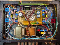
My kit has finally arrived and I'll start on it this weekend!
For my latest and, I think, final revision I combined the potential divider (for heater elevation) and bleeder with indicator LED into one unit since I was using a 300k bleeder resistor for the LED and, as luck would have it, the two resistors for the potential divider are 270k and 39k so I just stuck the LED at the bottom. Happy days!
Attachments
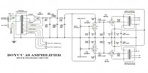
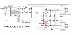
Schematic - May be helpful to newbies
Most likely at the wrong end of the forum but as the title says it maybe helpful. I tried many different free circuit drawing programs but ended up using just Photoshop Elements and juggling copies of the original sent with my kit. Hope it helps someone.
Most likely at the wrong end of the forum but as the title says it maybe helpful. I tried many different free circuit drawing programs but ended up using just Photoshop Elements and juggling copies of the original sent with my kit. Hope it helps someone.
Attachments
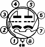
Hello DIYBobbie, i like well, it's well thinked but i don't see the link of pins 1 to 4 of V1 and V3. This link is it necessary into the schematic and into the build of amplifier.
Last edited:
Hi Learn.Hello DIYBobbie, i like well, it's well thinked but i don't see the link of pins 1 to 4 of V1 and V3. This link is it necessary into the schematic and into the build of amplifier.
Interesting that you mention that. I initially linked 1 & 4 on my build and I found that linking these pins actually caused problems. I can't recall just what the problems were now but my unit works well without linking 1 to 4
Maybe someone could enlighten me on why I had problems.
Attachments
Hi Bobbie,
I think by default we always connect 1&4, otherwise it seems only using half of the tube to amplify the signal. I never had trouble in this configuration. Later, since I had nothing to do, I borrowed Lima's idea (post #1082), I changed to parallel input to 1 and 4 with separate grid stoppers, separate bias resistors and bypass caps for 3 and 6. I guess I just created more work to do, and the result was no worse than previous design🙂
I think by default we always connect 1&4, otherwise it seems only using half of the tube to amplify the signal. I never had trouble in this configuration. Later, since I had nothing to do, I borrowed Lima's idea (post #1082), I changed to parallel input to 1 and 4 with separate grid stoppers, separate bias resistors and bypass caps for 3 and 6. I guess I just created more work to do, and the result was no worse than previous design🙂
Hi Daniellu,
Next time I have the back off my build I will try linking the pins and see what results are.
Next time I have the back off my build I will try linking the pins and see what results are.
A couple of small details changed on the schematic posted previously. Please disregard that schematic and refer to this new one---Most likely at the wrong end of the forum but as the title says it maybe helpful. I tried many different free circuit drawing programs but ended up using just Photoshop Elements and juggling copies of the original sent with my kit. Hope it helps someone.
Attachments

Faulty OPT..
I must be the most unlucky guy on this thread.
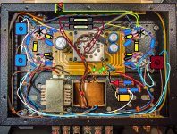
I finally built my A9, went to test it..
The heaters came on but there was no voltage across the rails. First tried with my 60w dim bulb tester which flared up then self down. Then a quick test without it and the rectifier began arcing.
I double checked my connections and was satisfied that everything was fine. Began making continuity checks and saw that the right 4 ohm speaker terminal was shorting to ground.
Upon further testing, BOTH B+ primaries of the OPT were also shorting to ground in addition to the right's blue feedback..
Sent an email of my woes to China hifi..
Now my confidence has been shattered.
Even if they send me replacements it's going to take another month and a half..
Alternatively if I were to buy better opts could anyone recommend any?
I must be the most unlucky guy on this thread.
I finally built my A9, went to test it..
The heaters came on but there was no voltage across the rails. First tried with my 60w dim bulb tester which flared up then self down. Then a quick test without it and the rectifier began arcing.
I double checked my connections and was satisfied that everything was fine. Began making continuity checks and saw that the right 4 ohm speaker terminal was shorting to ground.
Upon further testing, BOTH B+ primaries of the OPT were also shorting to ground in addition to the right's blue feedback..
Sent an email of my woes to China hifi..
Now my confidence has been shattered.
Even if they send me replacements it's going to take another month and a half..
Alternatively if I were to buy better opts could anyone recommend any?
A couple of small details changed on the schematic posted previously. Please disregard that schematic and refer to this new one---
The lower 6N9P should be rotated 180 degrees (to being upside-down).
Pins 2 and 5 are the plates; pins 3 and 6 are the cathodes.
Attachments
Correction needed
Yes you are right. A point overlooked. I will correct this in a revised post that I am working on shortly.
Thanks for your observation.
Yes you are right. A point overlooked. I will correct this in a revised post that I am working on shortly.
Thanks for your observation.
I am sorry for what happened to you. I stuck to the original design when I first built it. It was my first time dealing with tube stuff. I paid extra caution and tested every Rs , Cs, choke, transformers before start working on it. My usual job is operating on human being, I know pretty well why I only have one go and there is no chance to regret. I was lucky in building A9 in one attempt and it worked fine. Retrospectively, there are only a few mods be worthy of consideration for this amp and the original design is quite mature and works fine for most people.I must be the most unlucky guy on this thread.
Alternatively if I were to buy better opts could anyone recommend any?
I like my A9 so much that I decided to build a couple solid amps last year, I built a Hypex NC400 and a Icepower 125asx2 for fun. Hypex is fantastic in clarity and extreme low noise.
Since Covid 19 and isolation, I though life is short and I should spoil myself, so I bought my second tube amp: Cayin A88t.
Cayin A-88T MK2 Reference power amplifier Genalex KT88x4 tube integrated HiFi amp tested before send - YouTube
This video showed the exact one I have got. The seller (Yong Lee)is a good guy and he tested it for me before sending away (and post on youtube). This is a nice Amp, I probably will use it more now than the A9. but overall I think the sound probably a little bit better than A9.
other options, A10 is good too.
I also like this one:
Himing Rivals RH34W EL34 Tube Amplifier HIFI EXQUIS Wood Version Single Ended integrated handmade Scaffolding Amp|tube amplifier hifi|el34 tube amplifiertube amplifier - AliExpress
They are similar to A9 anyway. Good luck with everything!
Build Problems
Sorry to hear you had problems with your build but as Daniellu says I believe you over complicated your build from the start. Should have kept it simple and followed the supplied schematic. Then worked on mods after getting it up and running. I have looked at the schematic that you posted and had trouble understanding it. That said I am no expert.I must be the most unlucky guy on this thread.
I finally built my A9, went to test it..
The heaters came on but there was no voltage across the rails. First tried with my 60w dim bulb tester which flared up then self down.
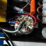
Pin 4 on the input tube appears to be disconnected.
How many schematics will repeat this error?
Most people do not read all the way through over 1000 posts.
Use separate grid stopper resistors on the input tube.
Of course, many of those amplifiers are on PCBs.
The question is, is pin 4 connected?
For those who build their own amp point to point from scratch, if they build according to the schematic, the triode with the floating grid will spoil the performance.
My Build Update
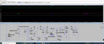
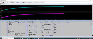
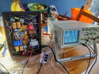
So, I disconnected the OPTs from B+.
Put the oscilloscope to the outputs of the coupling capacitors and, despite there being some distortion from the high voltage (395v @ B+), everything seems fine. The voltage was high because of the missing OPTs just as it was virtually non-existent two days ago because of the shorting OPTs.
Was getting 395V with the dimbulb tester and 409V without it but only for a few seconds.. I guess its times like these that a variac would come in handy..
Anyways, I'm now shopping around for two new OPTs - another opportunity for upgrading as I won't wait another 40 days for their replacements to arrive, once the email toing and froing comes to and end.
Attachments
- Home
- Amplifiers
- Tubes / Valves
- Boyuu EL34 A9 Tube Amp