Hey guys,
Early on, I ordered a 470uF/450V beast of a cap for C302 and two 33uF/450V for C301 and C303..
I put 2x470uF for C302 and it was all right. I switch on and off the amp 2-3 times a day and played 2-5 hours every day in the past year. No problems. the bass is better for sure.
I have to mention one modification to protect the rectifier tube, I put one UF4007 diode in series before going to pin 4 and pin 6 of the rectifier (you need 2x UF4007). the sparking inside the rectifier never happened.
Last edited:
Hi DIYBobbie/Ryan,
I went through all the posts here about 3 times , I can tell Ryan's Amp is A10. very similar to A9(apart from voltage amp stage). I would replace R107/108 (R207/208) with a single 470ohm 5w (or 6w), it's easy to go to Jaycar to pick up two. I don't know if there is other underlying issue caused this overheating problem, but it's a good start.
Hi Daniellu,
I did not know the A10 came with a full PCB, thought it was more point to point as per the A9. I stand to be corrected.
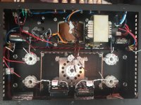
Hi all, I bought the amplifier brand new directly from the Chinese supplier, it has never been worked on by anyone and opened for the first time when Bob asked me to show internal pictures. So I guess at some stage they switched to a full circuit board. I am going to purchase the parts suggested and try and fix this myself, I’ll let you know 🙂
Hey guys.
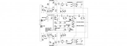
I've been playing around with LTspice and modeled the A9, albeit slightly modded with cathode resistor bypass caps and an artificial centre tap for both the first and second stage, although i plan on installing pots and since i couldn't find a model of the tube rectifier i had to settle for diodes. Also, since I don't know the specs of the OPTs I had to fudge with sensible figures and for some reason I can only crank it up to 20% volume, with a 2v input before distortion sets in.
The schematic contains both channels with separate adjustable voltage sources for you to play around and change test frequencies. I got it set up for 20 Hz and on side and 20 Khz on the other for kicks and giggles.
I searched for and downloaded tube models, namely 6N9S and EL34 and have installed them onto my copy of Spice but I don't know how to share them so if your copy of Spice hasn't got them the schematic won't work but I'm sure you guys and figure that one out. Anyways, have fun modding.
I put 2x470uF for C302 and it was all right. I switch on and off the amp 2-3 times a day and played 2-5 hours every day in the past year. No problems. the bass is better for sure.
I have to mention one modification to protect the rectifier tube, I put one UF4007 diode in series before going to pin 4 and pin 6 of the rectifier (you need 2x UF4007). the sparking inside the rectifier never happened.
Wow, Ok.
And what do you use on C301 and C303?
Hey guys.
I've been playing around with LTspice and modeled the A9, albeit slightly modded with cathode resistor bypass caps and an artificial centre tap for both the first and second stage, although i plan on installing pots and since i couldn't find a model of the tube rectifier i had to settle for diodes. Also, since I don't know the specs of the OPTs I had to fudge with sensible figures and for some reason I can only crank it up to 20% volume, with a 2v input before distortion sets in.
The schematic contains both channels with separate adjustable voltage sources for you to play around and change test frequencies. I got it set up for 20 Hz and on side and 20 Khz on the other for kicks and giggles.
I searched for and downloaded tube models, namely 6N9S and EL34 and have installed them onto my copy of Spice but I don't know how to share them so if your copy of Spice hasn't got them the schematic won't work but I'm sure you guys and figure that one out. Anyways, have fun modding.
An externally hosted image should be here but it was not working when we last tested it.
Boyuu A9.asc - Google Drive
Last edited:
Wow, Ok.
And what do you use on C301 and C303?
I left those 2 untouched. you can increase C301 a little bit, but I would not put a large Cap before the choke, this will kill the rectifier tube very fast. C303 (together with R302) is for decoupling for B2 power supple to voltage amplification stage, ideally 100uF -470uf would be better. I guess it doesn't matter too much.
Hi, I was considering doing a revamp of my unit without the PCB. After seeing your work I may well go ahead sometime. Looks more 50's era.....
Any chance of a schematic showing all the mods to the original.
Cheers,
Bobbie
Hi Bobbie
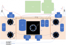
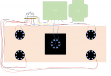
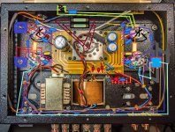
I never drew a schematic for my amp.... just some drawings to plan the layout and connections.
Mods:
Coupling Caps - Dayton Audio DFFC-0.47 0.47uF 400V
Cathode bypass Caps - 470uF 63V Mundorf ECap AC RAW and 0.01uF 650V Mundorf Mcap EVO in parallel
Pseudo center tap for the filament wires - 4 x Vishay 100Ω 3W Wire Wound Resistors
C302 - Vishay 450V 330uF capacitor
R102/202 - 470K 1W
R103/203 - 100K 2W
R104/204 - 2K 1W
R105/205 - 330K 1W
R106/206 - 100R 2W
R107,108/207,208 - 500R 6.5W
R301 - 33R 7W
R304 - 8.2K 7W
Lorlin power switch
Alps 100K volume pot.
For the Triode / UL switch - C & K COMPONENTS Toggle Switch, On-On, SPDT, 7000 Series, Panel Mount, 5 A
Smaller cathode bypass caps would have been nice but it fits so never mind....
The power input is grounded to the chassis right at the input
Transformer ground, heater preudo center tap and ground bus all ground to the chassis next to the choke. I removed some paint in both locations to get down to the metal.
The ground bus runs down each side, next to the valve bases and there's a wire connectng the relevant tabs on the terminal strip at the top.
The input grounds to the end of the ground bus nearst the volume pot.
I get zero hum, all of the voltages are in range and it sounds superb to my untrained ears....
Attachments
Hi Bobbie
I never drew a schematic for my amp.... just some drawings to plan the layout and connections.
.
Hi Bosch,
Thanks for the reply. I may take the time to draw up a schematic from what you have posted. When i get the urge to tinker again I may rip out the PCB and point to point my unit as you have done.
To make your unit complete why not integrate BlueTooth to play music via your iPad/mobile phone wirelessly. I did this with mine and is easily done with just 2 small components.
Great way to select/shuffle tracks to play as you relax with a scotch across the room on your lounge.
Cheers,
Bobbie
I use a Raspberry Pi running Volumio to stream music from my NAS through a DAC to the amp. Web browser on the iPad, from the lounge with a large scotch .... 
Blue Teeth
Hi Bobbie,
is fitting a BlueTooth feature something I could fit? Do you have a supplier of these?
Cheers Nick
Hi Bosch,
Thanks for the reply. I may take the time to draw up a schematic from what you have posted. When i get the urge to tinker again I may rip out the PCB and point to point my unit as you have done.
To make your unit complete why not integrate BlueTooth to play music via your iPad/mobile phone wirelessly. I did this with mine and is easily done with just 2 small components.
Great way to select/shuffle tracks to play as you relax with a scotch across the room on your lounge.
Cheers,
Bobbie
Hi Bobbie,
is fitting a BlueTooth feature something I could fit? Do you have a supplier of these?
Cheers Nick
I use a Raspberry Pi running Volumio to stream music from my NAS through a DAC to the amp. Web browser on the iPad, from the lounge with a large scotch ....
Wow that is all double Dutch to me. Much easier to say 'Bluetooth' But I like the 'large scotch' part
Last edited:
My Future Build
Ok, still waiting for my kit to arrive.
Been reading this forum up and down and Merlin Blencowe's excellent Preamp book and I think I've settled on the following mods:
1) Adding 2 500R pots, one for each stage and their wipers will be connected to the tops of the respective cathode resistors, hence better hum attenuation by way of voltage elevation of the filament leads. Hopefully the pots will be a perfect fit for the tube cage holes or with slight modding.
Here's a link to the pots:
3590 Wirewound Precision Potentiometer Pot 2W 5% - 100r to 100K | eBay
2) Fusing each HT coming off the PT into the rectifier.
Are 10 amp slow-blowing/delayed action fuses sized correctly?
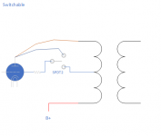
3) Adding a toggle switch for ultralinear/pseudo triode mode.
Here's the link for that:
Heschen metal toggle switch 3PDT maintained ON/ON 2 position 15A 250VAC 10A 380VAC CE: Amazon.co.uk: Car & Motorbike
4) Adding a power indicator led, fed off the preamp stage.
5) Adding axial 470uf/63v and 10nf/100v cathode bypass on every tube.
In addition to decreasing impedance they also isolate the stages from my elevated voltage heater circuit (without them they would motorboat - think that's the frase..)
6) Adding a feedback circuit between the stages.
(This really improved the distortion in LTspice)
7) Adding a bleeder resistor and LED on the power rail.
8) Adding a 0.1uf/600v cap alongside each power decoupling cap.
9) Replacing the original pot for an 100K ALPS
10) Replacing the original power switch for a Lorlin.
11) Swapping out C301 for 22uf/450V
12) Swapping out C302 for 450uf/450v
13) Swapping out C303 for 33uf/450v
14) Replacing R107/207, R108/208 with single 500R/5W resistors.
15) Adding 1k ohm grid stoppers to every tube.
16) Replacing the coupling caps with .22uf/630V, polypropylene axials.
Was going to go for .47uf but then got concerned about wobbly LF.
I'm considering adding diodes in series with the rectifier anodes for more protection but don't want more semi conductors in my amp.
What do you guys think?
Ok, still waiting for my kit to arrive.
Been reading this forum up and down and Merlin Blencowe's excellent Preamp book and I think I've settled on the following mods:
1) Adding 2 500R pots, one for each stage and their wipers will be connected to the tops of the respective cathode resistors, hence better hum attenuation by way of voltage elevation of the filament leads. Hopefully the pots will be a perfect fit for the tube cage holes or with slight modding.
Here's a link to the pots:
3590 Wirewound Precision Potentiometer Pot 2W 5% - 100r to 100K | eBay
2) Fusing each HT coming off the PT into the rectifier.
Are 10 amp slow-blowing/delayed action fuses sized correctly?
3) Adding a toggle switch for ultralinear/pseudo triode mode.
Here's the link for that:
Heschen metal toggle switch 3PDT maintained ON/ON 2 position 15A 250VAC 10A 380VAC CE: Amazon.co.uk: Car & Motorbike
4) Adding a power indicator led, fed off the preamp stage.
5) Adding axial 470uf/63v and 10nf/100v cathode bypass on every tube.
In addition to decreasing impedance they also isolate the stages from my elevated voltage heater circuit (without them they would motorboat - think that's the frase..)
6) Adding a feedback circuit between the stages.
(This really improved the distortion in LTspice)
7) Adding a bleeder resistor and LED on the power rail.
8) Adding a 0.1uf/600v cap alongside each power decoupling cap.
9) Replacing the original pot for an 100K ALPS
10) Replacing the original power switch for a Lorlin.
11) Swapping out C301 for 22uf/450V
12) Swapping out C302 for 450uf/450v
13) Swapping out C303 for 33uf/450v
14) Replacing R107/207, R108/208 with single 500R/5W resistors.
15) Adding 1k ohm grid stoppers to every tube.
16) Replacing the coupling caps with .22uf/630V, polypropylene axials.
Was going to go for .47uf but then got concerned about wobbly LF.
I'm considering adding diodes in series with the rectifier anodes for more protection but don't want more semi conductors in my amp.
What do you guys think?
Attachments
Last edited:
Overcomplicated and totally useless for the indirectly heated tubes.1) Adding 2 500R pots, one for each stage and their wipers will be connected to the tops of the respective cathode resistors, hence better hum attenuation by way of voltage elevation of the filament leads.
Just make the voltage divider out of two constant resistors between B+ and ground and tie your heaters there (any of the two wires). As long as divider provides voltage higher then the bias and is within max heater-to-cathode voltage parameters, you are OK.
10A is definitely too much. Simulate the PSU in LTSpice or PSUDII, find the RMS current through the PT secondary (after the initial surge), make the fuse 2-3 times more than that current.2) Fusing each HT coming off the PT into the rectifier.
Are 10 amp slow-blowing/delayed action fuses sized correctly?
I'm lazy to do this for you, but most likely you'll end up somewhere around 0.75-1A.
If your electrolytic caps are at least half-decent low-ESR ones, don't bypass them with anyting.5) Adding axial 470uf/63v and 10nf/100v cathode bypass on every tube.
That was a good idea like 50 years ago with early electrolytic caps, but with modern ones you'll just make things worse.
There are lots of topics on this subject here on the forum.
Again - don't.8) Adding a 0.1uf/600v cap alongside each power decoupling cap.
No objections on the other points 😎
Overcomplicated and totally useless for the indirectly heated tubes.
Just make the voltage divider out of two constant resistors between B+ and ground and tie your heaters there (any of the two wires). As long as divider provides voltage higher then the bias and is within max heater-to-cathode voltage parameters, you are OK.
10A is definitely too much. Simulate the PSU in LTSpice or PSUDII, find the RMS current through the PT secondary (after the initial surge), make the fuse 2-3 times more than that current.
I'm lazy to do this for you, but most likely you'll end up somewhere around 0.75-1A.
If your electrolytic caps are at least half-decent low-ESR ones, don't bypass them with anyting.
That was a good idea like 50 years ago with early electrolytic caps, but with modern ones you'll just make things worse.
There are lots of topics on this subject here on the forum.
Again - don't.
No objections on the other points 😎
Thanks for commenting.
I'll take onboard your advice about the fuses and caps, although mine are just normal electrolytic caps - nothing fancy.
Regarding your suggestion about setting up a voltage divider between B+ and ground and connecting that to the heater circuits... That's also voltage elevation.
I, by connecting the artificial center tap in between the Kr and the cathode elevates the heater voltage to bias anyways without any chance of going lower because it's connected to it directly and the pots would be located right by one of the parallel connected sockets. Even if I used two 100R resistors instead, isn't it easier to just connect them at the socket?
Further, even if I just grounded the resistors instead of elevation, well I could just connect that to the bottom of Kr.
Again, thanks for taking the time to comment.
Last edited:
You want to have the heater above the cathode, not at it (the cathode-heater pair is basically a diode which should be reverse-biased to kill the current conduction). And if you use AC for the heaters, half of the time they will be below the cathodes.Regarding your suggestion about setting up a voltage divider between B+ and ground and connecting that to the heater circuits... That's also voltage elevation.
I, by connecting the artificial center tap in between the Kr and the cathode elevates the heater voltage to bias anyways without any chance of going lower because it's connected to it directly and the pots would be located right by one of the parallel connected sockets. Even if I used two 100R resistors instead, isn't it easier to just connect them at the socket?
Further, even if I just grounded the resistors instead of elevation, well I could just connect that to the bottom of Kr.
I would still use the B+ voltage divider at least 10V above the bias. And it would most likely be the single divider for both 6SL7 and EL34 at something like 40-45V, there's no need for separate divider for the input stage.
You want to have the heater above the cathode, not at it (the cathode-heater pair is basically a diode which should be reverse-biased to kill the current conduction). And if you use AC for the heaters, half of the time they will be below the cathodes.
I would still use the B+ voltage divider at least 10V above the bias. And it would most likely be the single divider for both 6SL7 and EL34 at something like 40-45V, there's no need for separate divider for the input stage.
Ah, understood now!
6) Adding a feedback circuit between the stages.
(This really improved the distortion in LTspice)
What do you guys think?
Thanks for sharing your thoughts, I like most of them🙂
Regarding the feed back, I adopted 'KT88 Abdellah' version of anode follower , which i put in El34 stage (instead of voltage amp stage in your mod).
KT88 SE Abdellah (modified by Alex Gendrano) + AK.. | Page 10 | Audiokarma Home Audio Stereo Discussion Forums
YouTube
I put a 220K R between EL34 anode (pin 3) and 6N9P anode (pin 2,5 before the coupling cap C102). as you said, it improves distortion. but I like it in the way that it opens up sound stage for whatever reason. I never removed this negative feedback after my experimenting.
Attachments
Hi Danielle,I put a 220K R between EL34 anode (pin 3) and 6N9P anode (pin 2,5 before the coupling cap C102). as you said, it improves distortion. but I like it in the way that it opens up sound stage for whatever reason. I never removed this negative feedback after my experimenting.
When you say 'opens up sound stage' could another term for that be 'music throw'.
2watt resistor?
- Home
- Amplifiers
- Tubes / Valves
- Boyuu EL34 A9 Tube Amp