Hi OldHector,
How about the old simple rule of turning off the amplifier before messing with the speaker leads???
That's how I do when I switch the speakers, but my kids will also use the system so I want to add the safety 8ohm load resistors in case they forget to turn off the tube amp when the selector is for the receiver speakers
Fdlima
Hi OldHector,
How about the old simple rule of turning off the amplifier before messing with the speaker leads???
-Chris
You are right, of course, but there have been other debates about this practice here, and a conclusion from that was having a 400 ohm resistor wired across the terminals mitigated the risk of the speaker leads being pulled out by accident, and is used in music amps.
[FL] If it is as shown in your diagram In the post above, to wire in stereo I will need an 8 pole switch 🙂.
Ah, yes, good plint!
Hi OldHector,
Yes, a 400R resistor would be better than nothing, but make sure it can dissipate some heat for a while in case the amp is left on while playing program material (thinking of you Fdlima 🙂 ). I had three kids that were allowed to use the main system and it sometimes used a tube amp. I ran the speaker leads under the floor so you couldn't trip[ on them.
-Chris
Take a 35 Watt amplifier.
Put a 400 Ohm resistor on an 8 Ohm tap.
35 Watts into 8 Ohms is 16.7Vrms, or 23.7V peak.
The 400 Ohm resistor will dissipate no more than 0.7 Watts,
unless you turn the amp all the way up to clipping, 1.4 Watts in the 400 Ohm resistor.
But it will be even higher than that, because with the light load, the voltage will be higher than 23.7V peak.
The output transformer primary volts will go way too high.
And the output tubes, and / or the output transformer will be toast.
400 Ohms is not protection.
Not if you turn the amp up.
The best protection is people who pay attention to details, and are very careful.
Even the best protection circuitry may be subject to failure.
Parts fail, connections fail, etc.
Last edited:
The output transformer primary volts will go way too high.
And the output tubes, and / or the output transformer will be toast.
What does the feedback loop have to say about this?
Many amplifiers with, or without, negative feedback will far exceed their normal linear output voltage, especially without a proper load.
Turn the gains high enough, and it will either clip, or keep on going.
Negative feedback sets the gain of the amplifier.
Just try putting your foot on the gas pedal, all the way to the floor, and then put the car in neutral (no load).
Most amplifiers have excess gain, so you can turn up the quiet passages.
Not intended to do that at the loud passages (unless it is a guitar amp - wail on it,
and even sometimes break some of them)
First turn up all gain controls, preamp, power amp, etc.
Then how about full scale DAC output to the power amp?
Then how about when the RCA plug comes out just far enough so the ground is open, but the center conductor signal is still connected? HUMMMMM at or beyond full output.
No load (and extremely low load) condition is not good.
It is a common mistake when we run a stereo, if we do not hear anything, we turn the gain all the way up.
Then we set the input selector to connect the signal, and Blast!
Now, try that when you forgot to connect the speaker.
Your mileage may vary.
Last edited:
Hi All,
Thanks for all too good information but I still haven't heard a definitive answer if I can connect together the negative speaker wires from both amps, as shown in diagram.
Thanks, I appreciate your help.
Fdlima

Thanks for all too good information but I still haven't heard a definitive answer if I can connect together the negative speaker wires from both amps, as shown in diagram.
Thanks, I appreciate your help.
Fdlima
Hi Fdlima,
I wouldn't. You might get away with it sometimes, but then you might run into an amplifier or receiver you can't do that with. Generally not good design practice.
-Chris
I wouldn't. You might get away with it sometimes, but then you might run into an amplifier or receiver you can't do that with. Generally not good design practice.
-Chris
Fdlima,
First of all, you need a Triple pole, double throw switch. And you need a second 8 Ohm resistor.
You need to terminate the receiver speaker terminals too (even if it is a solid state receiver).
If you already have connected the receiver preamp out to the tube amp input,
without any damage to either,
And . . .
If the receiver preamp out RCA shield is Zero Ohms to the receiver speaker out Common lead.
And . . .
If the tube amp RCA line input shield is Zero Ohms to the tube amp speaker out Common lead,
Then . . .
It should be OK to connect the receiver common to the tube amp common.
Caution: Make the resistance measurements above, with both the receiver unplugged, and the tube amp unplugged,
and with all the inputs and outputs of both receiver and tube amp all disconnected.
That way, you are assuring that there internal DC connections in the receiver, and in the amp, individually, from their RCA shields and speaker Commons.
Last edited:
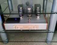
Hello All. I'm back!!
After about a month of lots of travels, I finally had time to work on my amp again this weekend. And I did a major mod that I wanted to share with you guys.
I installed vintage looking VU meters in the front of the amp, and I think it gave a good vintage look to the amp.
I got my VU meter kit for free from Nobsound because they screwed up the delivery of my A9 amp causing delays, but this kit can be bought on eBay.
2PC Panel VU Meter Amplifier DB Level LED Header Display & Driver Board Module 142372810396 | eBay
It does take a lot metal work skills to install these VU meters because you have a make a very clean hole in the aluminum front panel, and also some cuts in chassis front panel but it's worth it.
I bought and installed a 12Vac transformer to power the VU driver board because I didn't want to mess with using big resistors to reduce high voltage to 12 volt.
I can give you detailed instructions of how I installed these VU meters if you're interested.
Cheers.
Flima
Hi, can i have more info? Thanks
Fdlima,
First of all, your need a Triple pole, double throw switch. And you need a second 8 Ohm resistor.
You need to terminate the receiver speaker terminals too (even if it is a solid state receiver) . . . .
Hi 6A3sUMMER,
Thanks for you comments. They are always welcome.
I've checked the schematic diagram for my receiver and when receiver's speaker switch is in "OFF", the amp outputs are just "floating". they don't have load resistors, so, if the manufacturer didn't put load resistors, I will just leave without them.
I have done all the measuring and there are no voltages difference between the two amps, but I will order the correct switch and do it the correct way.
Best regards,
Fdlima

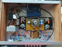
Hi All,
Over the Easter holiday weekend, my son and I built the speaker selector box that I was asking for some advices in previous posts. This project I was a great way to spend the weekend at home (since we are under "stay at home" order) and also, I was good to do things together with my sun.
The box evolved from a simple speaker selector box, to a more complex apparatus with additional source inputs and selector, VU meter, headphone jack, Bluetooth receiver, USB charger (the two last ones was a request from my son) and AC outlets controlled by the main power switch.
Here are some pictures of our project. BTW, I wanted to make this box to look as vintage as possible.
Components needed:

Drilled Panels:

Ready to Assemble:

My son helping me build:

Assembled (NOTE: the speaker grounds are connected together for now until the new switch arrives)


Box Completed

Box hooked up with the rest of the system:

And finally, the wiring diagram:

I hope you had enjoyed these pictures and please send me your comments because they are always welcome.
Cheers,
Fdlima
Over the Easter holiday weekend, my son and I built the speaker selector box that I was asking for some advices in previous posts. This project I was a great way to spend the weekend at home (since we are under "stay at home" order) and also, I was good to do things together with my sun.
The box evolved from a simple speaker selector box, to a more complex apparatus with additional source inputs and selector, VU meter, headphone jack, Bluetooth receiver, USB charger (the two last ones was a request from my son) and AC outlets controlled by the main power switch.
Here are some pictures of our project. BTW, I wanted to make this box to look as vintage as possible.
Components needed:
Drilled Panels:
Ready to Assemble:
My son helping me build:
Assembled (NOTE: the speaker grounds are connected together for now until the new switch arrives)
Box Completed
Box hooked up with the rest of the system:
And finally, the wiring diagram:
I hope you had enjoyed these pictures and please send me your comments because they are always welcome.
Cheers,
Fdlima
AC vs. DC heater supply
Has anybody tried to supply the heater with a DC voltage instead of AC? It is a mod that seems easy and cheap (diode bridge and Pi-filter) but would it bring something?
Has anybody tried to supply the heater with a DC voltage instead of AC? It is a mod that seems easy and cheap (diode bridge and Pi-filter) but would it bring something?
I hope you had enjoyed these pictures and please send me your comments because they are always welcome.
Cheers,
Fdlima
Neatly done! What does your son think of the 'tube sound'?
Cheers,
Fdlima
Neatly done! What does your son think of the 'tube sound'?
DIYBobbie
Hi All,
I am a new kid on this thread (82yrs young retired engineer)
My interest in tubes goes back over 50yrs ago when I put together a Playmaster tube tuner/amp which was a project in the then Electronics Australia magazine (some of the Aussies posters may remember that excellent publication).
Over the past 18mths I have put together an A9 amp. On receiving the kit I decided that I wanted to inter-grate a preamp with tone controls. (I had done this on an earlier amp by simply attaching a preamp with tone controls to the actual amp feeding into the inputs of the amp).
Of course I could not do this in the kit chassis so I purchased a 430x300x70mms aluminium enclosure from Doukmall. and went to work with various drills, files, hole saws etc,.
The end result is shown in the attached photos.
I have left the circuit stock standard apart from adding the 100 Ohm resistors (3x1 watt resistors in parallel due to unavailability of 3 watt resistors) to balance the heating line of 6N9PJ tubes to remove some hum that was evident when first fired up. It is now dead quite and I am delighted with the sound and will probably leave well enough alone until I get the urge to tinker further.
Oh, also I have built-in a Bluetooth board in order to play music via my iPad.
It has been interesting reading all past posts on the A9. Great forum.
Attachments
Of course I could not do this in the kit chassis so I purchased a 430x300x70mms aluminium enclosure from Doukmall. and went to work with various drills, files, hole saws etc,.
The end result is shown in the attached photos.
It looks pretty cool. Congratulations.
Since you have metal work skills, and have space in from panel, why not add VUs to make it look very vintage?
2 X Analog VU Meter Panel Kit Backlit Decibel/Level Tester with VU Driver Board | eBay
Please send us the link for the tube pre-amp.
Cheers,
Flima
Neatly done! What does your son think of the 'tube sound'?
Yes, my son, who's 21, really enjoys the sound of vinyls and tube amps.
BTW, after I finished the project I noticed newer iPhones were not recoginsing the USB port thus not charging. The USB port charged other generic devices but not iPhones (and probably not newer Android phones either, but I don't have them so I couldn't test it).
After doing some research on the web, and learning about lots of very complicated circuits to make Apple devices to recognize the charger, I found out that it only needs to short D+ and D- pins in the USB receptacle. The iPhones now charges fine with that USB port.
Here's the revised diagram for the USB port.
Regards,
Flima

It looks pretty cool. Congratulations.
Please send us the link for the tube pre-amp.
Flima
Hi Fdlima, Thanks for the suggestion re VU meters. I will give it some thought.
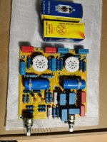
As for the pre amp at this stage I used a cheapy (photo attached) a dime a dozen on eBay, take your chose. However, I am surprised by the ‘tonal’ level achieved by this cheapy
Eventually I intend to use the one shown in the attached photo. It is also from eBay but is based on the PJ Baxandall tone control circuitry. It uses ECC86 S (12ax7) equivalent tubes and is supposed to be the ants/pants as far as tone controls go. To date I have not found a suitable power supply for it so I used the cheapy in the interim.
Attachments
Boyuu A9 Resisitor Issue
Hi I am very new to this site, I am also fairly new to electronics. I bought a made Boyuu A9 and it has operated perfectly then one day it made a noise and one channel failed, I relegated it to the shed.
Npow after moving I thought I would have a look uner the bonnet ansd I can see that the two resistors R207 & R208 have got so hot the colour codes and paint have blistered and obviously they have failed. There is slight burning around R108 but R107 still looks OK, I would like to replace these but do not know where to get spares and what values, I am assuming 1 K is the size?
Help would be appreciated. I am in Australia north of Port Stephens if there are any electronic wizards in the area?
Regards, Nick
- Home
- Amplifiers
- Tubes / Valves
- Boyuu EL34 A9 Tube Amp