Update to the build.
I bought an alps 27 100k pot. Was very hard to install had to modify the case slightly to get it in but it is installed. However weird thing is that the pot is somehow reversed, where the all the way right is where the volume starts and goes up counterclockwise. This though however fixed my right channel having little to no sound. now everything sounds balanced and awesome.
My only residing issue is the hum that still changes based on the position of the volume pot. I rearranged my grounding points and the hum has subsided some but it is still there. Can this amp be soundless if on with nothing playing or is that just a downside of tube amps?
Any insight would be most grateful. Thanks to everyone's input!
Hello XxBIGWOODxX, have you wired pins 7 of the "6n9p" and "El34" supports as explained by: "gregas" on page 46 (# 458) of this thread. It would be easier to help you by posting a photo of your amp.
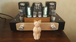
Thanks learn, will post here in a little bit. Getting the young ones asleep. Then I will master this item. Btw, it does sound fantastic!
ok i totally forgot about the about the gregas post. I finally just did it now, would like a final ok before i put it back together.
An externally hosted image should be here but it was not working when we last tested it.
OMG!!!!!! I have it all done and sewed up. This thing is now quite and hum free. It sounds amazing with my Fluance bookshelves.
Now waiting on cables to round out my desk set up with a SMSL SU-8 DAC and headphone AMP SMSL SP200.
Shout outs to everyone on here, thank you.
Now waiting on cables to round out my desk set up with a SMSL SU-8 DAC and headphone AMP SMSL SP200.
Shout outs to everyone on here, thank you.
Hello XxBIGWOODxX, this is great  . I am happy for you. I did not manage to see the photo of your amp but it does not matter. Well done, I hope I have helped you a little. See you soon.
. I am happy for you. I did not manage to see the photo of your amp but it does not matter. Well done, I hope I have helped you a little. See you soon. Hey guys,
I'm good for now? Do you see any problems? :/
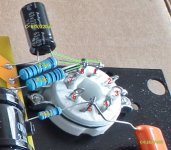
@learn can you give me some more detailed pictures of the inlay? I try to build the amplifier with your pictures. 🙂 For example I dont get the connection of the condensator and the resitors. 🙁
Thank you and best regards!
I'm good for now? Do you see any problems? :/
@learn can you give me some more detailed pictures of the inlay? I try to build the amplifier with your pictures. 🙂 For example I dont get the connection of the condensator and the resitors. 🙁
Thank you and best regards!
Attachments
-
 20200205_222303.jpg865.6 KB · Views: 187
 -
 20200205_222309.jpg978.9 KB · Views: 180
 -
 20200205_222315.jpg984.9 KB · Views: 142
 -
 20200205_222320.jpg978.1 KB · Views: 150
 -
 20200205_222326.jpg987.8 KB · Views: 140
 -
 20200205_222334.jpg1,000.6 KB · Views: 153
 -
 20200205_222345.jpg1 MB · Views: 167
 -
 20200205_222358.jpg986.6 KB · Views: 169
 -
 20200205_222407.jpg984.3 KB · Views: 162
Where is the wiring for the heaters? Normally that should go in first so that it can be routed out of the way to minimise noise in the final product.
Hey guys,
I'm good for now? Do you see any problems? :/
@learn can you give me some more detailed pictures of the inlay? I try to build the amplifier with your pictures. 🙂 For example I dont get the connection of the condensator and the resitors. 🙁
Thank you and best regards!
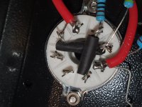
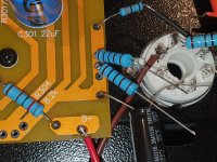
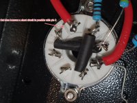
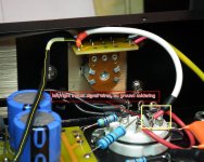
Hello 5e24ur5hio4, here is a photo (1) of the wiring of resistors and capacitor on pins 1 and 8. I also noticed that you should cut a long link between pin 1 and 2. see photo (2).😉
Attachments
Last edited:
Heater wiring (to pins 7 and 8) should go in first.
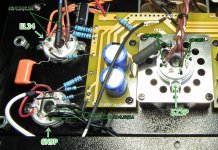
absolutely, heating wiring to pins 7 and 8 of the (6n9p) black wires of the power transformer (6.3V-AC / 1A) and to pins 2 and 7 of the (el34) orange wires also at the output of the power transformer (6.3V -AC / 3.5A).
Hello,
With two resistors for symetrical grounding for each 6,3V the hum is really reduced. I measure it at -56dBu.
I also add a mod with two EM84 as a vumeter.
With two resistors for symetrical grounding for each 6,3V the hum is really reduced. I measure it at -56dBu.
I also add a mod with two EM84 as a vumeter.

michel16,
By -56dBu, did you mean 56dB below 1 Volt rms?
Or did you mean 56dB below 0.7746V rms?
Thanks!
By -56dBu, did you mean 56dB below 1 Volt rms?
Or did you mean 56dB below 0.7746V rms?
Thanks!
...with a photo
Hello Michel, are you using the original potentiometer or another. Thank you.
Hello,
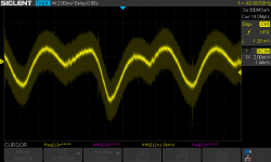
@6A3sUMMER, I made a little mistake with the calculation. In fact the hum is measured at -53dBu below 0,7746 Vrms on a 4 ohms load. And the hum is not pure 50Hz but has good harmonics as you can see on the screenshot (don't care HF noise due to electromagnetic pollution caused by modern power suplies nearby).
@learn, I do not changed the potentiometer, the problem was not here in fact...
Attachments
Last edited:
Addendum,erratum (post #1053)
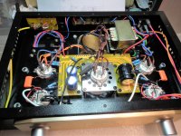
Hello, personally I wired like this:
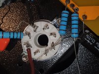
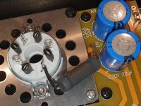
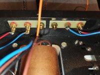
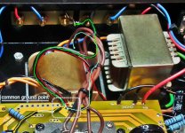
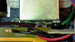
Picture 1: marked in green=0V speakers, marked in blue=0V power transformer, marked in red=chassis ground, marked in yellow=input audio signal ground.
**All wires goes to the common ground point on PCB.**
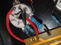
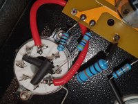
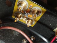
**For connection marked red and marked yellow see pictures 2 and 3**.
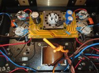
**For an overview see picture 4.**
PS: Note that 2 connection points are missing which are explained by: "gregas" on page 46 (#458) of this thread.
Hello, personally I wired like this:
Picture 1: marked in green=0V speakers, marked in blue=0V power transformer, marked in red=chassis ground, marked in yellow=input audio signal ground.
**All wires goes to the common ground point on PCB.**
**For connection marked red and marked yellow see pictures 2 and 3**.
**For an overview see picture 4.**
PS: Note that 2 connection points are missing which are explained by: "gregas" on page 46 (#458) of this thread.
Attachments
Last edited:
Hi guys! I appear on this thread around p. 28 when I built my amp in August 2017. Yesterday I decided to see the development of the thread since then and I was a little bit disappointed to find so many negative comments and claims about this amp.
I've been using this amp for ~10 hours each day, I often forget it turned on for days and it's been performing incredibly well. I use very sensitive speakers (The bass and mid from Klipsch R28-F and the tweeters from another set of Kenwood columns as the Klipsch's tweeters are too harsh) and:
1. No hum, virtually none with my ears close to these powerful columns
2. Great results in combination with an ODAC as a source.
The only issue I had was with the original rectifier which does it's job, but it rings mechanically in operation and to my ears it is a very annoying filament high-frequency ringing. Replaced it with a Russian 5Ц3С and problem fixed.
Why am I writing this...?
In the thread I saw so many:
- really bad ideas for improvements;
- so many people getting in touch with wiring and electronics for the first time;
- assessment and conclusions for bad quality in combination with pictures of horrific wiring;
- damaged components and even transformers ??!!
- replacing the first power capacitors with 100+ uF given that the original schematic uses 22~33uF (from a guy who claims he's an electronic engineer AND DOES THIS to a rectifier tube).
Please, before stating that the amp is bad, remember that a project like this requires some deep knowledge and maybe some experience with tubes, hum, electronics in general and ability to handle basic building challenges. And yes, I, like many others, have changed the schematic here and there but I did at my own risk and relying on a substantial experience and knowledge what I am doing, although I am not a professional electronic engineer.
Good luck, nice builds and a lot of fun to all of you guys!
Hi guys! I appear on this thread around p. 28 when I built my amp in August 2017. Yesterday I decided to see the development of the thread since then and I was a little bit disappointed to find so many negative comments and claims about this amp.
Yeah. I followed this thread avidly for a while, but gave up. I learnt an awful lot from it, but then branched out and found other material. [I've been a stickler for evaluating sources since before the internet - even more so since the '90s!]
I'm the one (or one of the ones) who fried his power transformer, but I hope I didn't blame the kit itself! I mis-wired some basic modifications: heater grounding resistors and cathode bypass caps on the triode. The biggest thing I learnt there is the price of ironwork!
My take-away from the whole experience:
- I have a great-sounding daily-use amp.
- I have learnt a lot.
- I enjoyed it and continue to learn/do.
- I'd recommend the same kit so someone else starting out, but only for someone willing to work at it. Not for someone who needs hand-holding through step-by-step instructions.
- looking at other sources, I suspect the cost of the kit is worth it just for the transformers and choke!
Next projects: build something around some ELC86's salvaged (with transformers) from an old radiogram; salvage more from a scrapped Hammond organ; etc, etc.
Cheers
- Home
- Amplifiers
- Tubes / Valves
- Boyuu EL34 A9 Tube Amp