Any builder of that amp, should check to see if the specific rectifier that is installed is an Indirectly heated model (has a real cathode, not just a filament).<snip>
Boyuu A9 uses 5Z3P, which is a directly heated rectifier.
- I was a bit paranoid about having only a single ground for the signal connections, and then only one connection of that to the chassis ground.
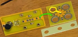
That’s absolutely true. As I have never experienced any hum noise since I first built this tube amp, I will share what I have done , which I think it’s important. In the picture one, I drew one mental piece there. There are 4 of those, I soldered all 4 together in the centre of the board (the middle of the cross). And I connected this board to the other one (on the left ) using a cable (ground). This will make sure there is no loose contact.
I would drill a hole in the middle of the cross, if I would build this a second time. And using a sparing resistor arm put in the hole and solder all the 4 tags together. The other thoughts about this amp:
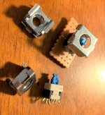
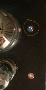
I am not good at making big holes in the steel panel to add a couple switches. In picture 2, I found this ‘M6 captive nuts’, and the ‘latching tactile push button switch’, I managed to mount it under any of the 4 holes in the tube side of the chasis. In that way I can have swtich(es) to change for UL/Triode , or different bias resistance. In picture 3 , I use a match stick to insert into the hole and push down the button to switch.
To be honest, in the end I think it’s not necessary to have switches. I like the Triode mode so much, I can’t stand UL mode. I can’t wait to switch back to Triode after I listened in UL for 10 minutes. I tried many times, interesting. Mostly I listen to jazz, triode is much better!
As for the bias , smaller Cathode resistor for EL34 (R107) doesn’t make the sound warmer to me , it is already warm enough for me. Anyway I use a smaller Cathode resistor for KT88 when I rolling tubes (it sounds good even R107 is 500 ohm).
I managed to increase the ripple filter capacitors (for B1), actually it is 1000uF now. I got the answers from forums that high capacity will not harm the rectifier tube as long as they are placed after the choke. Well, this’s not 100% true. The 5Z3P was sparking at the moment I turn it on!(considering the high charging current for large caps), surprisingly 5U4G doesn’t spark. I am sure sparking every time I turn on the cold amp is not healthy for the rectifier. It might be my faulty I have removed the 39 ohm (R301) for some time and it worked OK until I increased filter cap. ( I removed R301 just because I don’t like the idea for it sits there produce 5 watt of heat and doing nothing!) Well now I can see it prevents sparking, it never sparks again after I put the R301 back (only need to disconnect the short cable on top of it).
When I researched sparking issues, I found it’s good idea to put 2x diodes before the power transformer lines entering Pin 4 and Pin 6 (of 5Z3P). I did this simple modification using 2x UF4007, very good results, and I removed R301 again in the end. No more sparking. IMHO, the sound seems somehow different, and I like it. Also, before this, I can hear very faint baseline noise within 5-10 cm distance of the loud speakers, now they are dead quite . I am not sure if this has anything to do with the UF4007s I put in line .
Overall I am very happy with my A9 tube amplifier. I know there are people whinging about it. The baseline is, it’s a good product, with good design. If we build it properly with original parts, it sounds fantastic. I am happy to give it 10 years warranty I am sure it will never fail you. The A9 amp comes with 200 watt transformer (640v x0.25A +6.3v x4A+6.3v x2A +5v x4A=217.8 watt). Using the original schematic, overall power consumption is about 88 watt. It’s very safe to run it for prolonged time. The outside surface of the transfer is tepid after playing music for more than 4 hours, the surface is palpable with less the 40 degree(oC) .( it would be 50 degree if running KT88 for 4 hours)
The parts come with the kit are reasonably good quality, there is no issues just use it. By saying that, I received a faulty 5z3p, still I am not complaining. I measured every other parts before starting building it. Only thing I found was C301/303 (22uF) , the ones I got were 21.72uF and 22.28uF, I found the ESR was a bit high (2.8 ohm). Since I didn’t have replacement , I used them anyway. The coupling capacitor (0.22u) , they measured as 0.241uF and 0.232uF with ESR 0.71ohm. I think they are good enough, I am not silly enough to believe it will make any difference to the sound if swapped with ‘highend’ same capacity ones. Well , I modified to 0.47 uF in the end anyway. Also, the stock EL34s are not matched, at least I can see from weight, one is 53g and the other is 46g. I also purchased a pair of match Psvane EL34, they are both 53 gram. I found the Psvane EL34 sound same as Shuguang EL34, and they look identical too.
It is a DIY kit, we can change any parts if we are not happy. I was quite happy with the original schematics, but I modified and changed more than 50% of parts after using it over 3 months. As a matter of fact, I am very grateful that those Chinese sellers take care of the audiophile DIYer’s market. None of the other countries care about selling similar products, or with this low price and reasonable quality. Tube amps in general are very expensive if they are not made in China, on Ebay, the second hand McIntosh 240 :USD$3866,
If I have to complain, the Chinese sellers (in general) are stubborn. They don’t bother to translate their documents into proper English. They have Chinese document there and expect everyone can figure it out.
They are nice and genuinely try to be helpful, I believe. The communications are good in the way they always respond you promptly, but most ineffectively. They tried hard but they are simply incapable of communication in English.
My first tube device was the one I bought on Ebay a few months ago, 6J1 preamp/buffer. I liked it and I thought I will use it forever. I then bought some GE5654 and Chinese 6J1 tubes. The 6J1 tubes were so cheap ($1) and I bought a few, except none of them worked on my buffer! I never suspected they would sell me fake or faulty products. So I emailed the seller and asked for help. He was very polite and reassured me he will check with his tech support. I was puzzled about those not-working 6J1 tubes from China, after I measured and compared with GE5654, I found the Pin 2 and 7 should be internally connected, but those ‘faulty’ Chinese 6J1 are not. So I connected pin 2 and 7 on the PCB of the buffer amp, all fixed! Then I emailed again to the seller and telling him my findings, just in case other buyer like me would have the same question in the future, if he had not had the answer already. Then I got the reply from the Chinese ebay seller, He said, I am sorry for your trouble, How about I refund you for these tubes? In the end I took some effort and convinced him that’s not necessary at all. Of course this will not stop me from buying products from China.
Attachments
Last edited:
Daniellu already wrote that he received a chinese equilvalent of the 5U4GB in failure. Here the same!!!!! In my case the rectifier had internal short circuit. Luckily the fuse was blown but in other case it would have cost me the transformer.
After a lot of experimenting (switching on and off the amp for a lot, to search the source for the hum i measured), one EL34 was failing too. A lot of current was running through the cathode resistor and smoking began..
However, after these little problems i am very satisfied with the Boyuu amp. It is my second chinese amp. Some years ago i built a EL84 PP amp and i am also very satisfied with that amp.
Danellu, I don't know you but I find your approach strange, mainly about the power supply!
you create problems by modifying this one, and then bypassing them by opting for solutions that do not make sense if you restore a more normal power supply.
after, if you are happy and it works well to your ears, that's good, but the approach remains strange.
you create problems by modifying this one, and then bypassing them by opting for solutions that do not make sense if you restore a more normal power supply.
after, if you are happy and it works well to your ears, that's good, but the approach remains strange.
Hi Huggygood,I don't like the R301 (39 ohm) causing B+ voltage drop 5 volt. It creates about 1-2 watt of heat inside chasis, I checked many other schematics, this resistor design is not compulsory. But again, I thinks it's a good design, very safe design for A9 as a kit.
The sparking problem was only created when i put in total 1000 uF filter cap, I really like the large cap filter that brings on lovely bass. I would rather fix the sparking issue than reduce the filter cap. Then I have 2 options, one is put R301 back, the other one is, using UF4007 before the rectifier, both work well, the latter, I don't need R301. UF4007 prevents sparking and protects the rectifier (even you don't have a sparking problem) as many users recommended. I didn't expect any sound improvement just wanted to fix the sparking, subjectively I noted the sound is 'cleaner' after I put in UF4007, I am still not quite sure to be honest.
I tried not to take big risks , only the ones within reasonable range, it's fun to try and fail. Cheers, Daniel
Last edited:
having fun is not bad 🙂 so keep having fun !
I just finished assembling mine (all original) and for now, that's what I heard worse tube amp.
I will start to modify it by following the recommendations of the people who made this thread to see if an improvement is possible, but we must recognize that we start from very very low.
I just finished assembling mine (all original) and for now, that's what I heard worse tube amp.
I will start to modify it by following the recommendations of the people who made this thread to see if an improvement is possible, but we must recognize that we start from very very low.
I do not agree with you, Huggygood. In my opinion there is nothing wrong with the basics. Well, the transformer will get a bit too hot but after several hours playing its still working. Maybe the capacitors/elco's are counterfeit, but that's normal in China. That doesn't mean they can work properly.
I've built a similar chinese amp (el84 push pull) in 2012. Did some modifications on it and used it till my Boyuu was finished about a month ago.
If you are interested i can put some test results of my Boyuu amp here, with a 1 KHz squarewave at the input.
I've built a similar chinese amp (el84 push pull) in 2012. Did some modifications on it and used it till my Boyuu was finished about a month ago.
If you are interested i can put some test results of my Boyuu amp here, with a 1 KHz squarewave at the input.
Hi Daniel,
That 39 R resistor reduces hot switching currents, and of course the large charging currents. It doesn't affect the bass in any way. That, i suspect, is a case of confirmation bias.
Before you start "designing by ear", have a look at tube manual specifications for the tubes you are using and you will often find that something you don't see a need for actually has a very good reason to be there in the design.
The energy stored in a filter capacitor goes up as the voltage squared. 1,000 uF is massive and I greatly suspect another appearance of confirmation bias. Most older amplifiers that would deliver thundering bass had a single 47 uF capacitor with 400 ~ 450 volts on it. That 47 uF is also about the maximum recommended value allowed for most tube rectifiers. I feel 100 uF is excessive (and it is as far as rectifier tubes are concerned).
So testing various ideas is fine - as long as you stay within safe boundaries established by all the fine minds that existed before you appeared (or me for that matter).
-Chris
Hi Chris,
That 39R doesn't affect bass for sure.
As I mention above, the first cap immediately after the rectifier has it’s limited , I left as it is (22uf), I would not even risk to increase to 47uf, which is about the limit for the rectifier tube. Most people agreed there is no definite capacity limit about the filter cap after the choke. It’s not uncommon people use 470uf or 680uf after the choke. I agree I should have left the 39R there for safety reasons. In single ended tube amp, the large filter cap will not ‘stiffer the bass’ as it happens in push and pull amp, but I think larger cap will affect the sound quality in the way of reducing ripper current and hum.
The rectifier tube always works in tough condition, I am sorry I didn’t make its life any easier, I might put 39 R back.
Cheers,
Daniel
Hi Daniel,
No sweat. After a choke you can indeed increase the filter capacitance. However, I haven't seen really large filter capacitance help in the bass department at all unless you're at very high power - same as with a solid state amplifier. If you're running that high, chances are you are also clipping a fair amount.
Your 22uF first filter could probably be safely increased depending on the rectifier. 33uF is a commonly stocked value as well.
Your second filter capacitor can indeed help with supply hum. Another approach you can consider would be to supply your gain stages through a solid state regulator. You will probably find (hint) that this type of supply will also reduce all kinds of noise and signals in the background. That is dependent on how good that regulator is. That leaves your output tubes "open" to whatever is on the B+ voltage rails. Feedback will then decrease that noise because it is compared to a circuit that has a clean supply voltage. I have found regulators incredibly helpful to have. Any suggestion that you can hear a solid state regulator isn't accurate - as long as it works well and properly. I'd have suggested a tube regulator except they aren't quite as effective and the additional demands on the power transformer are valid concerns (budget, heat, complexity). Any argument that a regulator spoils the idea of a simple class A single output amplifier is forgetting that they were not using 470 uF supply capacitors, never mind 1,000 uF ones!
Anyway, you can try it and if it doesn't work for you, then use it for a bench supply when you are developing or testing preamp circuits. It won't be wasted.
These are only things you can think about and, hopefully, to try if you are curious at all. The higher the performance you can squeeze out of a project, the more likely it is that you will continue to enjoy it for years to come.
Best, Chris
@ hanskarel
"If you are interested i can put some test results of my Boyuu amp here, with a 1 KHz squarewave at the input"
Yes,i'm interested
"If you are interested i can put some test results of my Boyuu amp here, with a 1 KHz squarewave at the input"
Yes,i'm interested
Picked up one of these pre built off a well known auction site. Got it cheap as somebody built the kit and decided it was not for them, so I thought I would take the opportunity to see what these cheap Chinese amp kits can do 😉
I fired it up with 8r dummy loads and did some tests with the scope and sig gen. First, the signals were really jumpy and unstable, so I disconnected and checked all the components and wiring against the stock schematic. All the connections were present and components totally stock, but the soldering quality was dire. Some wires were actually rattling about on their crimps and valve sockets. I'm not having a go at the original builder, they did a good job of getting all the connection correct, but if you have ne or soldered before then it's no surprise the joints were pitifull.
After resoldering EVERY joint I repowered the amp and made some basic checks. All was well, voltages and currents as expected. The intermittent signals now were gone.
INITAL IMPRESSIONS:
The quality of the chassis is excellent, the tubes are ok, the iron is incredible considering the money that is charged. All in all excellent value for the money.
Now the bad points, performance is in MY opinion, rubbish. As stock there is a nightmare buzzing, one cannot get more than a couple of watts without horrendous distortion at any frequency, frequency response falls off after 10khz and forget about anything below 100hz. Full power was measured to be around 5W rms. Most of these problems relate to the output transformers and primitive design, but it is still excellent value for money, just needs a little reconfiguring 😉
I decided to see how much I could improve this little amp without changing any major components or spending loads of money. Read my next post to see how I modified one channel to see how far I could improve the performance of this little amp. I left the other channel stock as a comparison to avoid any placebo effect creeping in
Have fun all!
one cannot get more than a couple of watts without horrendous distortion at any frequency, frequency response falls off after 10khz and forget about anything below 100hz.
Do you have measurements (numbers, and test setup) for those problems?
This is what I did to one channel of my amp to try and increase performance.
First, the buzzing. We all know this one, floating heater filaments are to blame. Two 100r resistors centered tapped to ground on the preamp tubes stopped the buzz.
Next I tried wiring the el34 in triode mode to see if this helped. It did not do anything. I tried extra bias, this achived nothing as well. Seems the output transformers are the real limiting factor here.
To get around this problem without replacing the opt I decided to apply a generous dab of feedback. I know you are all throwing rocks at me as I type, but I just cannot let the little amp go to waste as I cannot bear to use it as it is.
So here goes, first I properly set up the biasing on the 6n9p as it was not very good. I did this by changing its bias resistor (r104) from 2k to 1k (my amp is the one with 75k at the anodes of the 6n9p triodes. Next i closed the feedback loop by connecting a 2k resistor and 10uf capacitor in series from the 8r tap on the opt to the cathode of the 6n9p preamp tube. Voila! After many measurements i was convinced this was the right way forward. To get maximum power at 50hz i also increased the quiescent current in the el34 by adding a third 1k resistor. This cleaned up the top half of the waveform below 100hz. After more measurments i added a 470pf cap accross the feedback resistor to clean up a little ringing on the edges of squarewaves. This still needs attention but i can live with it for now.
So, after the above mods the scope looks good. Clean waveforms right up to full power clipping with no visible distortion or flattening of the top of the waveform. Max power is now 22vPkPk or 7.5 Wrms. Bandwidth now 50hz to 60khz with no visible distortion, extending down to 20hz at full power with distortion, then down to below 10hz but horrible distortion. 20hz at 2w is fine, but more power causes distortion.
So 20hz to 60khz, clean squares and no distortion, whats the catch?
Well the catch is it now takes 8v PkPk to fully drive the amp. This is unacceptable, hmmm....
I decided to get around the input sensitivity problem by utilising the 'Spare' section of the 6n9p.
So i commenced by cutting the tube in half, using one half as el34 driver with the feedback loop still attached, the other half as an input preamp to reclaim my gain. So simply removing the connections tieing the two triodes together did the trick. After seperation i did not alter any component values as according to the data sheet they should still be appropriate. I powered up to check that the channel still worked as previous whilst running off one triode instead of two in parallel. It worked just fine and the tube was still biased at 1.5mA with anode biased around 170v.
Next i employed the now redundent triode inside the 6n9p as a preamp to boost the input. I used the 2k cathode resistor i removed previously and connected a 100k anode load resistor. I coupled the stages together with a 100nf capacitor and fed the audio input to the grid, using a 470k resistor as grid leak to ground.
After first power up all was not well, the channel was motorboating. Adding a 220uf capacitor to c303 solved this.
Success! Still had the previous performance of 20hz to 60khz flat, low distortion and 7.5Wrms. Input sensitivity was now 500mV.
The only downside to all this is one has to remember to connect the speakers back to front as the signal is now inverted LOL 🙂
IN MY OPIONION this little amp is now to my liking and working much better than it was when it was stock. Let me know your thoughts and please down burn me for using feedback!!
Have fun all and carry on building 😉
Last edited:
One last thing, cut out the capacitor that is accross the mains switch. It should not be there. If this was a DC mains supply then yes, the capacitor will reduce arcing and extend the switch life but mains is AC and this cap will pass a small amount of AC when the switch is off. Worst case is the cap will heat up and possibly cause a fire, apart from this its a waste of power. Best to remove it if you have not already.
Thats all for now!
@VictoriaGuy, what measurments are you looking for?
Have fun all, and stay safe 🙂
Thats all for now!
@VictoriaGuy, what measurments are you looking for?
Have fun all, and stay safe 🙂
thanks Nitrate
for the moment, I have applied only the "mods" of the wire and already it is better.
I tried 6l6gc, 6p3S-e and the best result for me is kt66 with 6h9c.
I will try your mods.
for the moment, I have applied only the "mods" of the wire and already it is better.
I tried 6l6gc, 6p3S-e and the best result for me is kt66 with 6h9c.
I will try your mods.
You mentioned the distortion, so I was wondering if you had measured THD, or used a spectrum analyzer, or some other method.@VictoriaGuy, what measurments are you looking for?
Certainly the numbers you quote after your mods are outstanding.
I'm also curious about your comment that pentode connection vs triode had no effect - usually doesn't this increase the power output?
I still have a lot to learn, so your mods are interesting to me.
Hi VictoriaGuy,
The THD has not been measured by the use of a hardware / software analyser. It is simply what i can observe on the oscilioscope. After many years of construction i get used to seeing distortions vs clean waves on the scope. When i can see the distortion it usally means its quite bad. When i can't see any distortion on the scope when overlapping the input and output it can still have distortion, but its usally under 2% when measured with an analyser. I don't have a computer in my workshop at the mo, so maybe sombody could try modding a channel on thier amp if they have access to distortion measuring equipment then post the results on here.
I do know that some people will be dissapointed if they reproduce my mods as it makes the amp somewhat linear and removes most of the harmonics that make the sound 'Tubey or Rich'.
Personally i like my amps linear and transparent, but these amps are by their nature very harmonically rich and that MAY be what people who use them like about them.
My comment about running in triode mode with no apparent change in the waveforms surprised me too. That was indeed what i witnessed. Normally the drastic reduction in output impedance in the tube normally improves wave distortions as there is more current available to drive the loads, but in this case it seems the lack of inductance in the OPT stops this from occuring. Maybe sombody with more knowledge about these things could chip in here and help us out.
This was just a weekend experiment just to pass the time, so nothing scientific here, Just having fun 😀
Congrats Nitrate!
I love my A9 so much and I listen a few hours everyday. I hardly use my newly bought Yamaha R-N602 these days. The final sound of A9 is an addiction.
Daniel
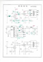
This is my final mod I drew the changes on it , It suits my taste and I decided to close the bottom cover and never open it again.. (in the near future)
I love my A9 so much and I listen a few hours everyday. I hardly use my newly bought Yamaha R-N602 these days. The final sound of A9 is an addiction.
Daniel
This is my final mod I drew the changes on it , It suits my taste and I decided to close the bottom cover and never open it again.. (in the near future)
Attachments
- Home
- Amplifiers
- Tubes / Valves
- Boyuu EL34 A9 Tube Amp