Good to hear my calculation was correct. I was thinking quarter watt for the grid resistors. What do you think?
Prices are a bit lower on 6SL7. Similar prices to TubeDepot are at TheTubeStore www.thetubestore.com - Tubes with part numbers beginning with 6SL7 TubeWow!! there is a big difference in prices depending on the letters that follow the part number!!
I've dealt with TheTubeStore and always had 100% satisfactory tubes. I've also dealt with Pacific TV in Victoria (John Albion) - he has tested used 6SL7 for $6. Pacific T.V. Tube Catalog eBay always has a good selection of tubes listed. I've had good luck with Russian/USSR tubes there.
I'm not very interested in 'tube rolling' with expensive tubes, so can't give advice on 'best choice'. It's rare to find anybody who has paid a lot for tubes, stating that they are not different-sounding than cheaper ones.
Don't forget the extra 1k grid stoppers. You should also get advice on the resistor type (metal film, carbon film, carbon composition) to use in each spot.What wattage should the 4k resistors be in mod we were talking about. I'm going to pick some up at the local electronic shop
BTW, a very good mail -order place for 'standard quality' resistors and caps is justradios.com Small business & they are located in Toronto.
Very good. I will check them out. Thanks. Does anyone have
any suggestions for grid resistors? metal film, carbon film, carbon composition?
any suggestions for grid resistors? metal film, carbon film, carbon composition?
Very good. I will check them out. Thanks. Does anyone have
any suggestions for grid resistors? metal film, carbon film, carbon composition?
Since nobody has jumped in with a recommendation...
I'd use metal film resistors for pretty much any spot in an amplifier.
I do see recommendations for carbon composition resistors but I don't know the rationale for that.
This article talks about resistors. In amps.
But I have no idea why someone would use carbon
Composition resistors if they are noisy.
Resistor Types - Does It Matter?
But I have no idea why someone would use carbon
Composition resistors if they are noisy.
Resistor Types - Does It Matter?
Fdlima,
How did you get to a 6L6 output tube, versus the EL34 output tube of the A9? ? ?
Be very sure of the B+ voltages in your amplifier, and other voltages too, before you convert the input stage to a serial (SRPP) stage.
Your voltages will vary according to your power line voltage variations, your power transformer turns ratio, your rectifier voltage drop, your output tube type, and will vary from one 6L6 to another 6L6 (or one EL34 to another EL34).
And the output tube cathode self bias voltage will vary with the self bias resistor value you use.
I will base my discussion below according to your schematic and voltages you provided.
Be careful, and re-check all your voltages if you do use the 6SL7 in that series mode:
Based on your schematic, there are certain voltages which may exceed the 6SL7 maximum specifications.
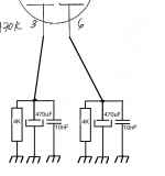
Do not forget to include the 270k, 56k, and 10uF capacitor to raise the 6SL7 6.3V filament to +65V.
The top 6SL7 cathode is at + 130V.
And the filament is at +65V
The maximum 6SL7 filament to cathode voltage is +/- 90V.
When the volume control is turned high enough, and when the signal is loud enough,
the top 6SL7 cathode voltage will go up another 23V until the 6L6 draws grid current
(it draws grid current when the grid goes +24V and the cathode self bias is at +23V).
130 + 23 = 153V.
153V - 65V = 88V
90V - 88V = 2V
You are only 2V away from the 6SL7 Maximum filament to cathode voltage of +/- 90V.
You can see that just a little variance in line voltage, tube to tube self bias voltage, resistor tolerance and accuracy, etc. can cause the circuit to exceed tube maximum specifications.
Which 6SL7 mode is better? . . .
Parallel operation should have 2 grid stopper resistors, 2 self bias resistors, and 2 bypass caps.
Parallel operation has a little more 2nd harmonic distortion (but that distortion partially cancels the 2nd harmonic distortion of the 6L6 or EL34 2nd harmonic distortion).
SRPP (series connection) gives a little more gain than parallel operation . . . do you need more gain?
SRPP has a little less 2nd harmonic distortion (which is less 2nd HD, so does not cancel as much of the 6L6 or EL34 2nd harmonic distortion).
Which one is better depends on what you want most, and what you like the sound of most, and how willing you are to check all the voltages, calculate the safety margins, etc.
Have fun modifying, and have fun listening.
How did you get to a 6L6 output tube, versus the EL34 output tube of the A9? ? ?
Be very sure of the B+ voltages in your amplifier, and other voltages too, before you convert the input stage to a serial (SRPP) stage.
Your voltages will vary according to your power line voltage variations, your power transformer turns ratio, your rectifier voltage drop, your output tube type, and will vary from one 6L6 to another 6L6 (or one EL34 to another EL34).
And the output tube cathode self bias voltage will vary with the self bias resistor value you use.
I will base my discussion below according to your schematic and voltages you provided.
Be careful, and re-check all your voltages if you do use the 6SL7 in that series mode:
Based on your schematic, there are certain voltages which may exceed the 6SL7 maximum specifications.
Do not forget to include the 270k, 56k, and 10uF capacitor to raise the 6SL7 6.3V filament to +65V.
The top 6SL7 cathode is at + 130V.
And the filament is at +65V
The maximum 6SL7 filament to cathode voltage is +/- 90V.
When the volume control is turned high enough, and when the signal is loud enough,
the top 6SL7 cathode voltage will go up another 23V until the 6L6 draws grid current
(it draws grid current when the grid goes +24V and the cathode self bias is at +23V).
130 + 23 = 153V.
153V - 65V = 88V
90V - 88V = 2V
You are only 2V away from the 6SL7 Maximum filament to cathode voltage of +/- 90V.
You can see that just a little variance in line voltage, tube to tube self bias voltage, resistor tolerance and accuracy, etc. can cause the circuit to exceed tube maximum specifications.
Which 6SL7 mode is better? . . .
Parallel operation should have 2 grid stopper resistors, 2 self bias resistors, and 2 bypass caps.
Parallel operation has a little more 2nd harmonic distortion (but that distortion partially cancels the 2nd harmonic distortion of the 6L6 or EL34 2nd harmonic distortion).
SRPP (series connection) gives a little more gain than parallel operation . . . do you need more gain?
SRPP has a little less 2nd harmonic distortion (which is less 2nd HD, so does not cancel as much of the 6L6 or EL34 2nd harmonic distortion).
Which one is better depends on what you want most, and what you like the sound of most, and how willing you are to check all the voltages, calculate the safety margins, etc.
Have fun modifying, and have fun listening.
Last edited:
Hi 6A3,
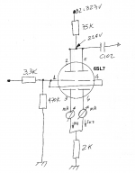
No, I did not make this mod in my amp. and this is not my diagram.
I found this diagram on the internet and I was "just curious" to know the advantages or disadvantages of using the 6SL7 as 2 triodes in series vs in parallel.
Cheers
No, I did not make this mod in my amp. and this is not my diagram.
I found this diagram on the internet and I was "just curious" to know the advantages or disadvantages of using the 6SL7 as 2 triodes in series vs in parallel.
Cheers
Fdlima,
I was not through re-editing my post #848 when your response (#849) came through.
I think I did cover the parallel and SRPP differences pretty well in my later edits of #848 (look at the bottom few sentences starting with "Which 6SL7 mode is better? . . .")
There is one other thing about an SRPP stage. The upper cathode sees the unbypassed resistor below it, in series with the plate resistance, rp, below that (that is a fairly high impedance). It is more likely to pick up the 6.3VAC signal onto the cathode (hum and line noise), even though it is elevated to a + DC voltage (i.e. +65V). You may have to select 6SL7s for low noise pickup of the filament 6.3VAC.
The cathode of the parallel stage sees a low impedance (the self bias resistor(s) and bypass cap(s) to ground). That means less possibility of picking up the 6.3VAC onto the cathode (less hum and line noise). You should Not have to select 6SL7s for low noise pickup of the filament 6.3VAC.
If you want the gain of the SRPP, but want to use one or two parallel 6SL7 triodes, just use an IXYS current source for the plate load of the single or parallel 6SL7 triodes. It will also be lower 2nd harmonic distortion than using a resistive load, RP.
Last edited:
The meaning of SRPP has been a mystery to me - I thought it had something to do with PP (Push-Pull) output (power) stages until recently.
This might help:
The Tube CAD Journal,SRPP Decoded
This might help:
The Tube CAD Journal,SRPP Decoded
VictoriaGuy,
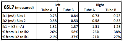
III. Now, this input triodes circuit has quite good DC balance, without selecting input tubes. Because you have separate 4k Ohm cathode resistors, you can easily read the voltage across each 4k resistor, and see how well the two triode DC currents match.
Hi 6A3,
Before modifying the circuit to add the 2x 4K cathode resistors, I decided made some measurements to see if the DC balance were off or not. And they are very unbalanced. (please see picture of how I did)
So in order to balance them I need to experiment with different resistor values until I find the correct values for Rk1 and Rk2. Example: Rk1= 4.7K and Rk2= 4K. Correct?
Also, the plate voltage on pins 2-5 seams to be high compared to what I've seen in some posts here. should In worry about this?
Thanks,
Attachments
I know you addressed your question to 6A3 - I'm sure he'll give a better answer soon.So in order to balance them I need to experiment with different resistor values until I find the correct values for Rk1 and Rk2. Example: Rk1= 4.7K and Rk2= 4K. Correct?
If it were my build I would use the same value resistors for Rk1 and Rk2 - i.e. 4k each. Otherwise,I think I'd be 'customizing' the circuit for a particular tube...what happens when I swap tubes?
The way that I would measure the current through each cathode would be to measure the voltage across a (known value) resistor. Even though I hve a couple of identical meters to measure current, I don't like 'breaking into' a circuit if I can avoid it.
In your example, I'd probably put a low-value (1,10,100 ohm) resistor in series with the 2k Rk and each cathode, and measure the voltage drop across each one.
Or, just go ahead and put the 4K resistors in and measure the voltage across them.
In most tube amp designs, 10% or more variation in voltages and currents is common. The Fender tube guitar amps had "+/- 20%" printed on the schematics.
In your example, I'd probably put a low-value (1,10,100 ohm) resistor in series with the 2k Rk and each cathode, and measure the voltage drop across each one.
Or, just go ahead and put the 4K resistors in and measure the voltage across them.
Hi VictoriaGuy,
Just to clarify, I did not add low-value resistors to the circuit. What I did was I opened the circuit(s), put my amperemeter in series and read the current(s) for the display. So the current values were not calculated. they were real values.
Cheers
Hi VictoriaGuy,
Just to clarify, I did not add low-value resistors to the circuit. What I did was I opened the circuit(s), put my amperemeter in series and read the current(s) for the display. So the current values were not calculated. they were real values.
Cheers
Yes, that was clear from your schematic sketch - thanks!
Either method will work OK.
Did you measure both currents at the same time - with two meters?
For me, currents calculated from voltage drops across resistors are accurate enough. New metal film or oxide resistors ('standard' not 'boutique') are quite precise values.
Did you measure both currents at the same time - with two meters?
Yes, I use to identical meters to measure the currents at the same time.
Frank
Fdlima,
The 4k resistors will give each cathode much more self bias control over its individual current. I have never used 6SL7 dual triodes, but you ought to be able to find some that have currents that are fairly well matched (IF you use individual self bias resistors).
Get 2 closely matched 4k Ohm resistors. Install them in the cathodes. Use a Voltmeter that is high resistance (a DMM, or a 20,000 Ohms per volt DMM). Measure the voltage across each 4k Ohm resistor, and calculate the current. Are they matched within about 20% or so? Call it good.
If they are more badly mis-matched than say 30%, try another 6SL7.
As to what your plate voltage is (higher than someone elses), there are lots of causes for differences: The tube you use versus the tube someone else uses The power transformer B+ secondary rated voltage, versus someone else's The DCR of your choke, versus someone else's The tolerance values of plate resistors, self bias resistors, B+ decoupling resistors. The output tubes that draw more or less current than someone else's. Your power line voltage may vary +/- 5% according to the hour of the day, etc. And power line voltages may vary more than +/- 10% from one location to another location.
And even if you build a kit the "same" as someone else's kit, there are no guarantees that the parts the company used today are identical to the parts they used 5 or 10 years ago.
Power line 3rd harmonic distortion causes peak voltage versus the RMS voltage to vary, the peak will no longer be 1.414 times the RMS. Someone with higher 3rd harmonic distortion will have a lower peak voltage (and power supply voltage of a capacitor input filter is dependent on peak voltage).
With all of those factors, what percentage was your plate voltage different versus someone else plate voltages?
Don’t use current sources in the cathodes. Don’t adjust the resistors up or down from 4k Ohms to make the currents match. Find some better matched tube(s).
I hope that helps.
Last edited:
Thank you 6A3,
I'm learning a lot from you.
I will install the 4K cathode resistors and let you know the current values.
BTW, I think the reason for my voltages to be higher might be because the AC mains here is 120VAC and the transformer is for 110VAC.
Cheers
I'm learning a lot from you.
I will install the 4K cathode resistors and let you know the current values.
BTW, I think the reason for my voltages to be higher might be because the AC mains here is 120VAC and the transformer is for 110VAC.
Cheers
If you are going to use bypass capacitors, then use individual ones for each individual self bias resistor.
1. Using a bypass capacitor can increase the voltage gain of the circuit. Using a bypass capacitor can increase the dynamic range of the circuit (maximum output voltage swing before clipping).
The amounts of the above effects depends on the tube: mu (u), transconductance, and plate resistance rp (these 3 are related, so any 2 of them defines the 3rd).
The amounts of the above effects also depends on the circuit resistances (cathode self bias resistance; plate load resistance, or current source plate load; and the grid resistor of the next stage).
2. With no bypass capacitors, the distortion is less due to degeneration (self negative feedback), up to a certain amount of voltage swing. But clipping will occur earlier because of the lower gain when unbypassed.
3. I have never used a 'second lower capacitance value bypass capacitor' across an electrolytic bypass capacitor. The same goes for B+ filter capacitors. I have not found it necessary in my circuits.
I used to do impedance tests of capacitors with a 10Hz to 4 GHz Vector Network Analyzer. I only tested out to a few Megahertz. The impedance starts out high(er) at 10Hz, goes lower as it continues through the audio range, and then goes to a minimum octaves above audio frequencies. After that the impedance rises again.
For some small capacitors, i.e. a 1uF non electrolytic, I could see the series self resonance of the 1 uF with the 2 Inch leads (inductance of 2 inches for each lead). That self resonance was multiple octaves above audio frequencies. Above that resonance frequency, the impedance is rising, because of the inductive reactance of the lead wires.
If you care about extremely high frequencies that are octaves above audio frequencies, you need to worry about the lead lengths of your circuits. Inductance increases with lead length, and so does inductive reactance. Except for unusual cases, lets not worry about this for tube audio amplifiers.
Last edited:
- Home
- Amplifiers
- Tubes / Valves
- Boyuu EL34 A9 Tube Amp