One question in this thread is whether there is enough current in the 6N9P, and a related question as to whether there is enough current to drive an ultra linear connected EL34 miller capacitance. I was not addressing those questions.
Separate to those questions, there is a parallel triode input stage. Parallel triodes that are set to low, medium, or high current can all benefit from individual bias for each triode.
The 3 listening venues that were used to illustrate the point, were done with parallel triodes that had individual bias circuits. That is why the listeners did not detect a difference between parallel and not parallel.
In the past there have been many who state paralleled tubes do not sound good. That is because some parallel tube circuits are not designed correctly. That was the reason it was researched for 2 years, and was the basis of the article in Glass Audio.
Hey Guys.
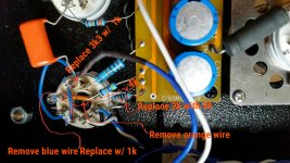
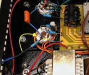
I think this is what you are saying. Replace the 3.3k grid resistor with a 1k resistor on pin 4 add a 1 k resistor on pin 1. i have it going from pin 4 to 1 remove the orange connection from pin 3 and 6 have a 2k resistor going from 3 and another going from 6 to ground
Can i not do it just as I've shown in the picture? why do i need a solder lug strip. I've never used one.
Attachments
If you could draw a quick schematic (just take a pic of a hand-drawn schematic - nothing fancy), it would be a bit easier for me to understand.Can i not do it just as I've shown in the picture? .
Thanks.
Sorry for the confusion. The the reason why I edited that picture with the proposed layout was so that you can see exactly where the new resistors would go to the circuit board. I've made a sketch it's pretty much the same as VictoriaGuy's sketch
Attachments
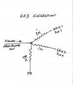
The 470k grid resistor should be moved from the tube socket, according to 6A3's suggestion.
That's why I said:
The circuit will probably 'work' with several different wiring arrangements, but if you want to implement 6A3's suggestions you need to find a connection point.
That's why I said:
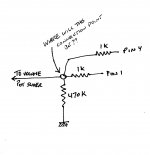
The important thing is that the grid stoppers connect right to the tube socket (close), and the 470k is not connected to the tube socket - as pointed out by 6A3, all the connections to the grid have to 'go through the stopper'. So you may have to find a new spot to join the two grid stoppers, the 470k resistor, and the volume control wiper. If the volume control is close enough, you could use it for the connection point.
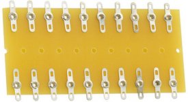
It's not a good idea to make joints 'in mid air' but it seems to be done fairly often, so that could be a last resort. You may have a spot nearby to connect a solder lug strip with a couple of (non grounded) connection points.
The circuit will probably 'work' with several different wiring arrangements, but if you want to implement 6A3's suggestions you need to find a connection point.
Attachments
Last edited:
I don't think so, and I don't think making all connections on the tube socket agrees with your last sketch either.
Sometimes it's useful to try drawing the same circuit in different ways.
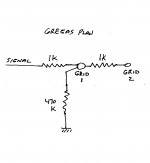
Part of the idea here is that the two grids should 'be the same'. Think of how the 'signal' gets from the volume control to the two grids - the paths should be identical. Also the way that each grid connects to the 470k grid resistor should 'be the same'.
Sometimes it's useful to try drawing the same circuit in different ways.
Part of the idea here is that the two grids should 'be the same'. Think of how the 'signal' gets from the volume control to the two grids - the paths should be identical. Also the way that each grid connects to the 470k grid resistor should 'be the same'.
Attachments
VictoriaGuy,
I. Thanks for posting a drawing of the grid circuit I wrote about, but I did not make it clear enough. Your drawing should make it clear to all.
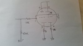
II. Also, it should be noted that in the other schematics, the individual input triodes cathodes should connect through individual 4k Ohm resistors to ground (pin 3 to 4k Ohm, other end of 4k to ground; and pin 6 to a second 4k Ohm resistor, and the other end of that second resistor to ground).
Note: use matched 4k Ohm resistors.
III. Now, this input triodes circuit has quite good DC balance, without selecting input tubes. Because you have separate 4k Ohm cathode resistors, you can easily read the voltage across each 4k resistor, and see how well the two triode DC currents match.
Rather than spending your time to do IV below, there may be other areas of the amplifier that might be better to pay attention to, etc. Instead, if the DC currents of the input triodes is not balanced, just swap out tubes until you get one that is better matched. Do not worry about a 10% or 15% mismatch of cathode voltages, but do worry about a 30% mismatch.
IV. The only other / additional way to make the circuit even more balanced is not normally needed. It is way too much (as some say: Over the Top), and not really worth doing:
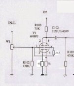
A. Remove the 75k Ohm input tubes plate load resistor.
B. Connect pin 2 through a 150k Ohm resistor to B2.
Connect pin 2 to C102, the 0.22uF cap (do not connect C102 to pin 5).
Connect the other end of C102 to the top of R105.
C. Connect pin 5 through a 150k Ohm resistor to B2.
Connect a second (added) 0.22uF cap to pin 5.
Connect the other end of that second 0.22uF cap to the top of R105.
Now, each triode has its own cathode resistor, its own plate resistor, and its own grid stopper resistor. Whatever is not DC balanced is caused by:
1. non matched triodes
2. non matched cathode resistors
3. non matched plate resistors
Or, a combination of two or 3 of the above factors.
I. Thanks for posting a drawing of the grid circuit I wrote about, but I did not make it clear enough. Your drawing should make it clear to all.
II. Also, it should be noted that in the other schematics, the individual input triodes cathodes should connect through individual 4k Ohm resistors to ground (pin 3 to 4k Ohm, other end of 4k to ground; and pin 6 to a second 4k Ohm resistor, and the other end of that second resistor to ground).
Note: use matched 4k Ohm resistors.
III. Now, this input triodes circuit has quite good DC balance, without selecting input tubes. Because you have separate 4k Ohm cathode resistors, you can easily read the voltage across each 4k resistor, and see how well the two triode DC currents match.
Rather than spending your time to do IV below, there may be other areas of the amplifier that might be better to pay attention to, etc. Instead, if the DC currents of the input triodes is not balanced, just swap out tubes until you get one that is better matched. Do not worry about a 10% or 15% mismatch of cathode voltages, but do worry about a 30% mismatch.
IV. The only other / additional way to make the circuit even more balanced is not normally needed. It is way too much (as some say: Over the Top), and not really worth doing:
A. Remove the 75k Ohm input tubes plate load resistor.
B. Connect pin 2 through a 150k Ohm resistor to B2.
Connect pin 2 to C102, the 0.22uF cap (do not connect C102 to pin 5).
Connect the other end of C102 to the top of R105.
C. Connect pin 5 through a 150k Ohm resistor to B2.
Connect a second (added) 0.22uF cap to pin 5.
Connect the other end of that second 0.22uF cap to the top of R105.
Now, each triode has its own cathode resistor, its own plate resistor, and its own grid stopper resistor. Whatever is not DC balanced is caused by:
1. non matched triodes
2. non matched cathode resistors
3. non matched plate resistors
Or, a combination of two or 3 of the above factors.
Last edited:
Ok. I get how the two layouts are not the same.So if I use a solder lug strip how do I secure it? Screws
Glue? I've never used one.
Glue? I've never used one.
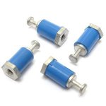
The usual way is with a machine screw (aka small nut and bolt) if using a metal chassis. Often one of the solder lugs is the extension of the attachment bracket - so it will be a 'chassis ground' connection. Make sure you don't absent-mindedly use it for a 'non-ground' connection.
Not that I would ever do that....😱
I will say that nowadays I often slip a piece of heat shrink on that ground lug as a reminder....
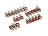
Solder lug strips come in various lengths and configurations, and are handy things to have on hand.
Insulated turrets and tag strips are also useful if you are stocking your parts bin.
Not that I would ever do that....😱
I will say that nowadays I often slip a piece of heat shrink on that ground lug as a reminder....
Solder lug strips come in various lengths and configurations, and are handy things to have on hand.
Insulated turrets and tag strips are also useful if you are stocking your parts bin.
Attachments
Hi,
This might be a stupid question but I'm asking anyways!
Looking at the EL34's datasheet I noticed that pin 6 is not used. Can I use pin 6 of the valve socket as a solder terminal to solder R106/206 to the output transformer wire? That would avoid me to having to buy a solder terminal just for that.
Thanks
Attachments
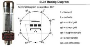
You can use pin 6 as long as you do not do tube-rolling with other types of tubes that do have a connection to pin 6.
I believe that most other tubes with similar characteristics to the EL34 usually do not use pin 6.
A KT77 is probably closest to an EL34, except that the EL34 has to have a connection to
pin 1, which is the Suppressor Grid, and that Suppressor Grid needs to be connected to pin 8, the cathode.
The KT77 does not have a connection to pin 6, and does not have a connection to pin 1.
Last edited:

Hi,
My A9 Amp has about only 20 hours of use and it started to have a hum on left channel only (the right channel works fine). The hum is not too loud and it’s masked when I’m playing music but it’s quite noticeable in silence between songs.
I believe the problem is in the 6N9PJ tube for the left channel because the hum moves with the tube when I swap the tubes left to right.
I made some measurement and I found lower voltages on the 6N9PJ tube with hum: Pin 2-5 is 124V and pin 3-6 is 1.1V. (on the good tube Pin 2-5 is 193V and pin 3-6 is 2.6V). and when I swap tube these voltages follow the tubes indicating that the problem is in that tube.
But, besides the hum, it plays music fine. So, since I’m new to tube, should I wait and see if it fixes itself after the burn-in time? Or it’s time for me to buy new pre-amp tubes?
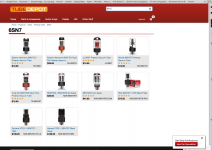
If I have to buy new tubes, which one do you recommend? I’ve seen some posts saying 6SN7 is a good tube.
And when can I buy them here in the USA?
Thanks for the help.
Frank
My A9 Amp has about only 20 hours of use and it started to have a hum on left channel only (the right channel works fine). The hum is not too loud and it’s masked when I’m playing music but it’s quite noticeable in silence between songs.
I believe the problem is in the 6N9PJ tube for the left channel because the hum moves with the tube when I swap the tubes left to right.
I made some measurement and I found lower voltages on the 6N9PJ tube with hum: Pin 2-5 is 124V and pin 3-6 is 1.1V. (on the good tube Pin 2-5 is 193V and pin 3-6 is 2.6V). and when I swap tube these voltages follow the tubes indicating that the problem is in that tube.
But, besides the hum, it plays music fine. So, since I’m new to tube, should I wait and see if it fixes itself after the burn-in time? Or it’s time for me to buy new pre-amp tubes?
If I have to buy new tubes, which one do you recommend? I’ve seen some posts saying 6SN7 is a good tube.
And when can I buy them here in the USA?
Thanks for the help.
Frank
gregas,
The 4k resistors can be the same wattage as the 2k resistor you are using and have extra power margin.
here is why:
The voltage across each 4k resistor should be about the same as the single 2k resistor.
But the current in the 4k will be only 1/2 of the current in the 2k.
Power = Current Squared x R
P = I squared x R
(1/2 of the original current) squared is 1/4. R is 2 times (4k versus 2k)
I squared is 1/4 of what it was, and R is 2 times what it was, so the power in the 4k resistor is 1/2 of what it was in the 2k resistor.
I also had one bad tube. Similar to you.
6sl7 is what you want to get not 6sn7.
Thanks, Where did you buy yours?
Wow!! there is a big difference in prices depending on the letters that follow the part number!!
Which one is recommended to the A9 Amp?
Thanks
Attachments
If the 4k can be the same wattage as the 2k. I need to calculate the 2k.
I=V/R
So I measured 2.6vdc on pin 3 or 6
So 2.6/2000
=.0013amps
P=IxV
.0013X2.6=.00338 watts
Does that calculation look correct?
I=V/R
So I measured 2.6vdc on pin 3 or 6
So 2.6/2000
=.0013amps
P=IxV
.0013X2.6=.00338 watts
Does that calculation look correct?
P=IxV
.0013X2.6=.00338 watts
Does that calculation look correct?
Yes.
However, I wouldn't use less than a 1/2 watt resistor there, mainly because anything less would be a bit on the small and fragile side for my taste. Also, usually, higher wattage resistors seem to have longer leads, which can be convenient if the connection points are a bit far apart.
- Home
- Amplifiers
- Tubes / Valves
- Boyuu EL34 A9 Tube Amp