I don't often think that my test gear is the problem. Good call!Thank you for the response. I went over to my dad's and borrowed his meter. I get 6.6vac with his meter. So my meter must be out.
Having a couple of 'meters', and extra probes and leads is always useful.
Years ago I bought some cheap alligator clip leads and discovered that a couple of them didn't have the insulation stripped before the ends were crimped on!
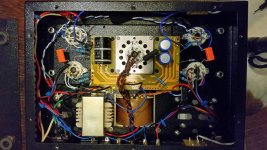
Is there anything in particular that you'd like folks to look at?This is what my amp currently looks like.
Well my issue is harshness at louder volume. I'm going to double check the wiring today as you suggested In terms of hum it's quiet. Still trying to get my hands on an scope. Also I'm considering other grid resistors aside from the 3.3k I got in now.
Well my issue is harshness at louder volume.
Maybe the amp is clipping? What speakers are you trying to push with this amp?
jeff
navydiver,
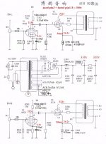
The schematic of post # 609, shows input tubes V1 and V3 have unbypassed cathode resistors.
If the tubes have filament to cathode leakage, that could cause hum.
Are you using the same circuit?
Swap input tubes V1 to V3, and V3 to V1; then listen again.
I do recommend two resistors, one from one end of 6.3V, and the 2nd from the other end of 6.3V, and the other ends to ground (a virtual center tap to ground) try two 47, 50, or 100 Ohm resistors.
Do not just tie one end of the 6.3V to ground, that is unbalanced.
Be sure to connect Both grids of each input tube. The schematics all show pin 4 not connected.
Do not let pin 4 float. These are parallel triodes. But because they share plate load, and share cathode resistors, it is even more important to use grid stoppers to partially isolate] the grid connections from each other.
Use 2 separate grid stoppers for each tube, 1k Ohms each. Connect one end directly to the tube socket tab # 4.
Connect the other ends to the resistors to the grid resistor that goes to ground, and to the volume control wiper.
Now, swap the output tubes to the opposite channel.
The B+ filter choke is under, or near-under one of the output transformers. Depending on the orientation of the two magnetics versus each other, that could cause hum.
Steel (non stainless) chassis conducts magnetic hum everywhere.
Otherwise, it sounds like one of two things:
A ground loop in one channel (ground return Locations of input triode grid resistor, cathode resistor, output tube cathode resistor), or input connections of RCA phono input jack, volume control and grid resistor, and Where they return to ground.
A wire that has hum (6.3 AC), or B+ wiring from transformer, rectifier, or first or second capacitor that comes near a sensitive point (grid of input tube, grid of output tube).
Are the DC voltages on both channels about the same?
(Plates, Cathodes, of both input, and both output tubes)
The closest thing to Navy Diving I have done is to swim 50 Meters underwater from end to end without taking a breath along the way.
Last edited:
Can you tell me how to do that without employing feedback?
Without feedback? I have no idea. Edelweiss-3 has 3 nested feedback loops, one of them is of course positive. It is similar to motor controllers in tape recorders that kept the speed independent on load.
Wavebourn,
Thanks. I do like to find new things, if they exist.
That is what I thought, no such kind of voltage increase of loaded versus unloaded, without having a feedback path.
I am still learning, but if I can only start remembering.
Three nested feedback loops, wow!
I would research all your techniques, but do not have that much time to do that.
Good luck on selling some Edelweiss amplifiers, or info, or whatever.
As to feedback loops, many of them have similar characteristics:
Overshoot
Undershoot/delay
Hysteresis
And sometimes Open loop
A few of the earliest feedback loops:
Insulin/sugar loop
Heart rate loop
Breathing rate loop
Balance
Eye tracking
etc.
Last edited:
I've got it hooked up to paradigm monitor 7 towers .
With those speakers, your amp is probably just not powerful enough to play real loud.
Anyone know a place here in Victoria, BC where I can buy inexpensive replacement tubes so I don't have to wait forever for an out of town order?
You have EL34's in your amp? Some of the guitar stores here probably have some. I have some old Shuguang's here that you can use as testers if you like. They worked fine in my amp, but have been sitting collecting dust for a few years.
jeff
Last edited:
Try John Albion at Pacific TV.
He's a very honest and straightforward guy, runs his business from his home now, so 'by appointment', I think.
Or send me a PM. 🙂
try swapping tube from the left side to the right side. does the problem follow?
i will try the amp with other speakers. I spent a few hours and I've double checked all the wiring it looks good to me. I did notice that there is a discrepancy from the wiring diagram and the actual components i got.
capacitor c301 and c303 should be 22uf 400v instead they are 33uf and 400v
capacitor c302 should be 150uf 450v instead it is 200uf 400v
capacitor c301 and c303 should be 22uf 400v instead they are 33uf and 400v
capacitor c302 should be 150uf 450v instead it is 200uf 400v
As to feedback loops, many of them have similar characteristics:
Overshoot
Undershoot/delay
Hysteresis
And sometimes Open loop
A few of the earliest feedback loops:
Insulin/sugar loop
Heart rate loop
Breathing rate loop
Balance
Eye tracking
etc.
Nested loops versus a single loop is the way to achieve needed results that would be impossible with a single loop. What I get as the result? Hundred kilo Hertz bandwidth with almost no ringing using cheapest Chinese transformers like in the kit of the topic, diminishingly low IMD up to the half power, but still soft asymmetric clipping on full power, and damping factor better than can provide solid state amps with dozen paralleled output transistors.
I don't think those should cause any worry; I don't think changes in the power supply filter caps would cause a difference in sound quality ('harshness').I did notice that there is a discrepancy from the wiring diagram and the actual components I got.
capacitor c301 and c303 should be 22uf 400v instead they are 33uf and 400v
capacitor c302 should be 150uf 450v instead it is 200uf 400v
Sounds pretty good to me - you ought to try 81 meters on Heliox and a hot water suit. You sound like Donald Duck in a hot tub😉The closest thing to Navy Diving I have done is to swim 50 Meters underwater from end to end without taking a breath along the way.
The schematic of post # 609, shows input tubes V1 and V3 have unbypassed cathode resistors.
If the tubes have filament to cathode leakage, that could cause hum.
Are you using the same circuit?
Swap input tubes V1 to V3, and V3 to V1; then listen again.
Thank you for your patience. Had my channels reversed in the video but same effect. In essence read left channel hum and no right channel hum because the unit was sideways I had the speaker wires inverted when I shot the video. Anyway I went ahead and flipped V1 with V3 tubes as suggested and repeated. No change in effect. It did not flip over to the other channel.
I do recommend two resistors, one from one end of 6.3V, and the 2nd from the other end of 6.3V, and the other ends to ground (a virtual center tap to ground) try two 47, 50, or 100 Ohm resistors.
Do not just tie one end of the 6.3V to ground, that is unbalanced.
I am really confused by the meaning of the above statement. On both V1 and V3 I have the secondary 6.3V heater power going to right channel pins 2 and 7 via twisted black wires off the Pwr transformer. From right pins 2 and 7 I have a twisted pair yellow of black relaying power to the left side tube socket pins 2 and 7. I then have a 100ohm resistor off of each pin 2 and 7 going into a Yon a red wire that goes to the circuit ground on the PCB. THis drawing more accurately represents my wiring for this project that I found much earlier in this thread as the component values represented what I had in my kit that did not agree with the crappy Chinese schematic I received.

I do recommend two resistors, one from one end of 6.3V, and the 2nd from the other end of 6.3V, and the other ends to ground (a virtual center tap to ground) try two 47, 50, or 100 Ohm resistors.
Do not just tie one end of the 6.3V to ground, that is unbalanced.
Sorry, lost me in translation. I am more drawing oriented as I have no frame of reference as to what an "end" means😱
I do recommend two resistors, one from one end of 6.3V, and the 2nd from the other end of 6.3V, and the other ends to ground (a virtual center tap to ground) try two 47, 50, or 100 Ohm resistors.
Do not just tie one end of the 6.3V to ground, that is unbalanced.
Yeah, same as my above comment mostly - If I catch the drift of what you are saying here, I thought I had done this... Do I do this V2 and V4 too?
Be sure to connect Both grids of each input tube. The schematics all show pin 4 not connected.
Do not let pin 4 float. These are parallel triodes. But because they share plate load, and share cathode resistors, it is even more important to use grid stoppers to partially isolate] the grid connections from each other.
Use 2 separate grid stoppers for each tube, 1k Ohms each. Connect one end directly to the tube socket tab # 4.
Connect the other ends to the resistors to the grid resistor that goes to ground, and to the volume control wiper.
See better (so I thought) schematic I used above - it shows that pin 4 is connected as well - thoughts on this schematic?
More comments of yours with my answer in red (Quotes are becoming bothersome)
Now, swap the output tubes to the opposite channel. - Have not tried this yet in light of new schematic but will do shortly.
The B+ filter choke is under, or near-under one of the output transformers. Depending on the orientation of the two magnetics versus each other, that could cause hum.
Steel (non stainless) chassis conducts magnetic hum everywhere. Several others including Smittie this forum have reported success with this design so I have to think it works and that I am doing something else wrong at this stage rather than blame the design at this juncture...
Otherwise, it sounds like one of two things:
A ground loop in one channel (ground return Locations of input triode grid resistor, cathode resistor, output tube cathode resistor), or input connections of RCA phono input jack, volume control and grid resistor, and Where they return to ground. Possible
A wire that has hum (6.3 AC), or B+ wiring from transformer, rectifier, or first or second capacitor that comes near a sensitive point (grid of input tube, grid of output tube). I was lead to believe that 60Hz hum was usually a tube failure as per the the second Youtube link in my post #692
Are the DC voltages on both channels about the same?
(Plates, Cathodes, of both input, and both output tubes) Here are my earlier measurements - will do an updated set of measurements right after posting.

see(pic)Yeah, same as my above comment mostly - If I catch the drift of what you are saying here, I thought I had done this... Do I do this V2 and V4 too?
View attachment 728580
pick up a pass capacitor 102 202
Humble Homemade Hifi - Cap Test
be sure to match the input signal to the 750 mV amplifier
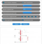
Voltage Divider Calculator
Attachments
see(pic)
pick up a pass capacitor 102 202
Humble Homemade Hifi - Cap Test
be sure to match the input signal to the 750 mV amplifier
Voltage Divider Calculator
You found changing cap 102 and 202 gave you improvements?
Can you further explain the voltage divider calculator. I don't get it.
http://www.humblehomemadehifi.com/download/Humble%20Homemade%20Hifi_Cap-Test-Ratings.pdfYou found changing cap 102 and 202 gave you improvements?
Can you further explain the voltage divider calculator. I don't get it.
The selection of a capacitor affects the sound quality; under my link you can read the results of using a particular capacitor, there is also a rating for them.
Humble Homemade Hifi - Cap Test
WIMA MKP 10
Technical specifications (according to manufacturer): "Pulse capacitor. The construction principle of the series WIMA MKP 10 consists of a non-metallized dielectric film and an carrier film metallized on both sides acting as electrode. Thanks to the metallization on both sides, the electrical conductivity is considerably improved and the contact surface between the electrodes and the schoopage layer is doubled. This results in better contact and allows for high current and pulse loading capability. The properties of metallized capacitors such as excellent self-healing and high volume capacitance remain unchanged."
Sound: With the WIMA MKP 10 you get a neutral, smooth and well balanced capacitor. For this price range the amount of transparency is quite reasonable and overall the MKP 10 is pleasant to listen to. Compared to the similar shaped and sized Mundorf RXF the presentation is more forward and a fraction less clear. But never the less it has good overall sound qualities. Don't forget to give it some time to burn-in. Fresh out of the box they sound restricted and dynamics are limited. After several weeks of use they should open-up.
Verdict: 8
A voltage divider is needed to match the signal level from the source to the amplifier.
Suppose your CD player or DAC outputs a 2v signal to the RCA, the amplifier has an input of 750 mv, for good operation, you need to equalize the values, a voltage divider is used for this.
You enter the necessary parameters into the calculator; it shows which resistors to use.
Sorry for my bad english
Last edited:
- Home
- Amplifiers
- Tubes / Valves
- Boyuu EL34 A9 Tube Amp