Back to the grounding issues.
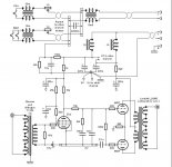
Here is the schematic diagram of a RIAA preamp. You can imagine how more sensitive it is than your amp, capable of picking up hums and noises!
The author very carefully drew how ground wires have to be connected If you follow it exactly, there will be no hum.
Here is the schematic diagram of a RIAA preamp. You can imagine how more sensitive it is than your amp, capable of picking up hums and noises!
The author very carefully drew how ground wires have to be connected If you follow it exactly, there will be no hum.
Attachments
Hi navydiver,
Love your Poodle! We have a Silver Standard and we're getting a rescue today, a "Woodle", a cross between a Soft Coated Wheaten Terrier and a Poodle. It retains the Poodle's personality and smarts, not that the Weaten isn't like that to start with.
Sorry for the OT. Love your dog.
-Chris
Thank you - Our dog Chloe is now 10 years old and is a Cocka-pooh although she is high percentage Poodle I guess. Hope you enjoy your new Woodle as much as we do our little best friend

As an aside I just received a new on/off switch as recommended herein as well as an ALPS volume control to hopefully improve the chintzy ones that came with the Boyuu.

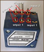
Alas, got no instructions with the ALPS so wondering if anyone knows the proper convention for mounting one of these bad boys on the daughter board so the volume goes up the right way? Would it be A or B?
Here is A

Here is B

Here is the Daughter board images alone (both sides)


Here is A
Here is B
Here is the Daughter board images alone (both sides)
The usual 'convention' with PCBs is that the components go on the side of the board with the silkscreened labels.
There's no need to trust that though.....a minute or two with the multimeter and schematic will tell you the answer.
Or, you could just cut into an old RCA cable and tack the pot into place between the CD player and the amp input on another amp - sometimes a quick experiment is the easiest way to get an answer.
I have the same pot in my preamp, just without the pcb. I'll have a look at it, and double check the connections. Personally, I wouldn't use the daughter board.Alas, got no instructions with the ALPS so wondering if anyone knows the proper convention for mounting one of these bad boys on the daughter board so the volume goes up the right way? Would it be A or B?
Edit: Ok, the connections in the image check with mine.
jeff
Attachments
Last edited:
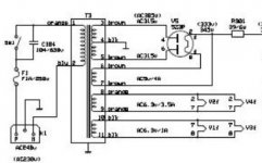
Hey guys. I'm trying to measure my voltages at pin 4 and 6 of the rectifier tube. Where would I put my negative lead from my multimeter?
Check out the schematic:
Those pins are connected to the (HV) secondary winding of the power transformer, so they will have AC voltage present (no DC). So you need to put your voltmeter on 'AC' volts, and at the correct range to handle the voltage you expect (>650 volts ? between the rectifier plates; half that between the center tap and the end of the HV winding).
With AC there's no 'positive' or 'negative' meter lead. You can measure the voltage between the center tap of the secondary and each of the rectifier plates. The center tap should be grounded to circuit ground, so one lead could be clipped there.
Be careful- I'd usually use clip leads for that measurement rather than the probes. Clip the leads on and then power up the amp, power down before removing leads.
Once you move to the DC side of the rectifier (pin 8?) you'll need to switch your meter to DC volts.
Be careful - if you are nervous, it's easy to slip with the probe, so it's safer to use alligator clip leads when doing this.
Attachments
Hey guys
so I've spent some time taking some measurements on my a9. What do you guys think?
B1 346 VDC
B2 326 VDC
EL34B PIN 3 ANODE 336 VDC
4 GRID 342 VDC
8 CATHODE 24 VDC
6N9P PIN 2 OR 5 ANODE 193VDC(left tube) 201 (right tube)
pin 3or6 CATHODE 2.6VDC
523PT leads on PIN 4AND6 480VAC
PIN 8 362DC
so I've spent some time taking some measurements on my a9. What do you guys think?
B1 346 VDC
B2 326 VDC
EL34B PIN 3 ANODE 336 VDC
4 GRID 342 VDC
8 CATHODE 24 VDC
6N9P PIN 2 OR 5 ANODE 193VDC(left tube) 201 (right tube)
pin 3or6 CATHODE 2.6VDC
523PT leads on PIN 4AND6 480VAC
PIN 8 362DC
Gregas:
That looks pretty reasonable to me, but I'm no expert. For the EL34, pin 4 (G2) is usually referred to as 'Screen'. I usually expect the screen voltage to be less than the plate, but after reading a bit at:
Relationship between screen voltages and plate voltages in power tubes
I understood better. No problem there.
BTW Pin 5 (G1) is usually referred to as 'The Grid'.
Now, knowing that you have the cathode at 24v above ground with the cathode resistor(s) you have, can you calculate the plate dissipation in Watts? That's a useful number to know.
Last edited:
So i found this online.
Measure cathode resistor, write it down as Rk. (500)
Measure Screen resistor, write it down as Rs. (100)
Power amp up and let it warm up.
Measure voltage across Rk and write it down as VRk. (24 )
Measure voltage across Rs and write down as Vrs. (342)
Measure plate voltage and write down as Vp. (336)
Turn amp off, and get your calculator out.
VRk / Rk = Ik or cathode current, write it down. 24/500=0.048
VRs / Rs = Is or screen current, write it down. 342/100= 3.42
Ik - Is = Ip or plate current, write it down. .048-3.42=-3.372
Now, Ip X Vp = IPD or Idle Plate Dissipation. For a single-ended-cathode-biased-amp it must not exceed the Max plate dissipation
-3.372x336= -1133
This doesn't seem correct. I must be doing something wrong 😕
Good work- you figured out that Rk=500 ohms, which can trick some folks.So i found this online.
Measure cathode resistor, write it down as Rk. (500)
Measure Screen resistor, write it down as Rs. (100)
Power amp up and let it warm up.
Measure voltage across Rk and write it down as VRk. (24 )
Measure voltage across Rs and write down as Vrs. (342)
Measure plate voltage and write down as Vp. (336)
Turn amp off, and get your calculator out.
VRk / Rk = Ik or cathode current, write it down. 24/500=0.048
VRs / Rs = Is or screen current, write it down. 342/100= 3.42
Ik - Is = Ip or plate current, write it down. .048-3.42=-3.372
Now, Ip X Vp = IPD or Idle Plate Dissipation. For a single-ended-cathode-biased-amp it must not exceed the Max plate dissipation
-3.372x336= -1133
This doesn't seem correct. I must be doing something wrong 😕
I don't think you have measured the voltage drop across the screen resistor (100 ohm?) yet. That's the Vrs in the above list.
0.048 A or 48mA is correct for the 'cathode current'. The screen current is usually pretty low, so a lot of folks just use Ip=Ik for rough calculations.
Also, you want to (eventually) check both channels (R&L) to make sure they are both OK.
I don't think you have measured the voltage drop across the screen resistor (100 ohm?) yet. That's the Vrs in the above list.
I measured pin 4 and i got 342 vdc. What i should of done was cut the shrink wrap over the resistor and measure voltage before it and after ? The difference would be the drop?
The screen current is usually pretty low, so a lot of folks just use Ip=Ik for rough calculations.
so 1000mA ?
I measured pin 4 and i got 342 vdc. What i should of done was cut the shrink wrap over the resistor and measure voltage before it and after ? The difference would be the drop?
The screen current is usually pretty low, so a lot of folks just use Ip=Ik for rough calculations.
so 1000mA ?
That would work. The usual method is to put one probe at each end of the resistor and measure the voltage drop. If you think about it, that's what you did when you measured the voltage at the cathode. One probe was connected to circuit ground ('bottom' of resistor); the other probe was on pin 8 (cathode, or 'top' of the resistor). The 24v was the drop across the Rk.I don't think you have measured the voltage drop across the screen resistor (100 ohm?) yet. That's the Vrs in the above list.
I measured pin 4 and i got 342 vdc. What i should of done was cut the shrink wrap over the resistor and measure voltage before it and after ? The difference would be the drop?
If the screen resistor is just soldered on to the end of the wire from the transformer, you'd have to cut back the heat shrink or slip the probe under the heat shrink or puncture the insulation with the probe - yes. If there's a connection point between the transformer wire and the screen resistor, measure there. Of course the other probe can go on pin 4.
No, I think you calculated 48mA for the current through the cathode resistor, so you could use that value for the current flow through the tube from plate to cathode - assuming the screen current is only a few mA.The screen current is usually pretty low, so a lot of folks just use Ip=Ik for rough calculations.
so 1000mA ?
Last edited:
Hi gregas,
Measuring the way you did can be very inaccurate. You should connect a DVM across the resistor. Hands completely off now, turn the amp on and take your reading across the resistor. Turn it off and once the voltage has died down, remove the clips and your meter.
Most meters do not measure high voltage accurately. To trust those readings the way you took them, you would have to be using:
Hand held meters, a Fluke or Keysight
Bench meters, Keysight, Keithley and maybe some specific other meters.
Watch the maximum safe voltage rating of your meter.
Why is this? Because the meters I mentioned use voltage dividers on a common ceramic substrate with excellent voltage and temperature characteristics. Other meters typically use normal resistors on the PCB. They do not have good characteristics at higher voltages, and they will not track thermally. High frequency response is typically very good on those meters I mentioned. A characteristic of film decade dividers that they use.
I have lots of meters I use. The normal ones are used for very non-critical uses at low voltages where I will say something like "about 9V", or something like that when measuring a 9V battery. My good meters are all Fluke, HP, Agilent and Keysight. Those meters also stay in calibration - unlike the normal ones. I'm not telling you to go send a fortune in meters. Just use what you have in a way that it will deliver a true reading for you. The good meters come over time. you almost can't have enough meters, I'm looking at 4 digital multimeters in my bench racks. They all have things they do best, and if I ever need accurate readings, I can absolutely trust them. Same for my good hand held meters. A couple Fluke and 5 Keysight / Agilent / HP meters. The old HP 974A has a basic DC accuracy of 0.05% and a 100 KHz bandwidth. Keep your eyes peeled for these used, they are an outstanding value. Old FLuke 87's would be the same deal, plenty of them and cheap used.
-Chris
Having a couple of meters is a good thing. I have 3. One can read ripple down to 100uV. For one 2 meter example, when you have one meter across the screen resistor, and you shut the amp off, your second meter can check that the B+ is getting to a safe voltage or not, before you go to disconnect the first meter (maybe your bleeder resistors burned open or maybe they take 3 minutes to drag the B+ to a safe value). Safety First!
I do use a DMM that is accurate to 1 kHz. But I use the scope for measurements above that (25 MHz at = -3dB). It can auto-measure peak, peak to peak, rms, cycle rms, min, max, phase, etc. It also has cursors; an FFT spectrum; and XY modes.
I use a 2500V 200MHz scope probe on the 25MHz scope to measure anything more than 300V. That probe divides the voltage down 'Before' the scope input, so that the AC coupling capacitor in the scope only sees 25V when the input to the probe is 2500V.
Test equipment is one of my specialties. I started calibrated measurements in 1959.
Happy testing of your amp, and happy listening!
Last edited:
+1 Multiple meters (and extra clip and 'grabber' leads/probes for them) are very handy. Cheap digital meters and analog ('needle') meters (cheap ones or good old ones from hamfests or yard sales) have their uses.Having a couple of meters is a good thing. I have 3. One can read ripple down to 100uV. For one 2 meter example, when you have one meter across the screen resistor, and you shut the amp off, your second meter can check that the B+ is getting to a safe voltage or not, before you go to disconnect the first meter (maybe your bleeder resistors burned open or maybe they take 3 minutes to drag the B+ to a safe value). Safety First!
For monitoring B+ or working on a guitar temolo circuit, an analog meter does a great job. For calculating plate dissipation and checking power supplies and general troubleshooting, I don't think a 'lab-grade' meter is necessary. I'm happy with my UNI-T 139C DMM, and my collection of cheaper meters. I also have a couple of HP bench meters (3466,3435) which I got cheaply on ebay years ago-it's sometimes nice to have something visible on a shelf, above the work surface.
Thanks for all the advice guys. here's the calc. with the voltage across the resistor.
Measure cathode resistor, write it down as Rk. (500)
Measure Screen resistor, write it down as Rs. (100)
Power amp up and let it warm up.
Measure voltage across Rk and write it down as VRk. (24.1 )
Measure voltage across Rs and write down as Vrs. (.344)
Measure plate voltage and write down as Vp. (336)
Turn amp off, and get your calculator out.
VRk / Rk = Ik or cathode current, write it down. 24.1/500=0.0482
VRs / Rs = Is or screen current, write it down. .344/100= .00344
Ik - Is = Ip or plate current, write it down. .0482- .00344=.04478
Now, Ip X Vp = IPD or Idle Plate Dissipation. For a single-ended-cathode-biased-amp it must not exceed the Max plate dissipation
.04478x336= 15.04608 watts
does this make more sense?
Looks good to me!Now, Ip X Vp = IPD or Idle Plate Dissipation. For a single-ended-cathode-biased-amp it must not exceed the Max plate dissipation
.04478x336= 15.04608 watts
does this make more sense?
I'd round off the result to 15 Watts.
Good work!
Now, the other channel...
🙂
If you run the tube 'too hot' - i.e. close to, or above the maximum rating plate dissipation for that tube- you can get 'red plating' where the inside of the tube overheats. It shorten$ tube lifetime - a lot.
Usually you'll see tubes run at 60-70% of the maximum plate dissipation.
If you are building an amp 'from scratch', you'll often have to change the cathode resistor value (from what the schematic may specify) to get the right plate dissipation, with the B+ voltage your power supply is delivering.
Some manufacturer's EL34 tubes can stand more abuse than others. I think Tubelab (George) probably has some info on that. 🙂
- Home
- Amplifiers
- Tubes / Valves
- Boyuu EL34 A9 Tube Amp