That's a good idea for dealing with high-level input signals, because most (ganged) stereo volume pots 'track' better in the middle of the adjustment range than near the minimum (loudness) positions, according to what I read.You understood correctly. So the volume control works in full
you need to lower the input signal to the specified value in the characteristics of the amplifier.
So the channel-to-channel balance will be maintained.
(Amplifiers should have a balance control anyway IMO, but that's a different topic...)
With the Boyuu A9 which has two switched inputs (NavyDiver showed this in his pics/videos), it would be easy to have one 'Hi' and one 'Lo' level input if desired.
I'd still like to see some scope waveform info to see where the clipping/distortion is originating, but the Boyuu is a bit expensive for me to buy as an experiment. 🙂
It shows the low labour costs in China when the assembled version is only a few dollars more than the kit. I was surprised when I looked on AliExpress.
The project is developingThat's a good idea for dealing with high-level input signals, because most (ganged) stereo volume pots 'track' better in the middle of the adjustment range than near the minimum (loudness) positions, according to what I read.
It shows the low labour costs in China when the assembled version is only a few dollars more than the kit. I was surprised when I looked on AliExpress.


There are plans to install a trimming cathode resistor, since when changing the output lamps it is necessary to adjust the output stage of the amplifier.
Attachments
That's a good idea for dealing with high-level input signals, because most (ganged) stereo volume pots 'track' better in the middle of the adjustment range than near the minimum (loudness) positions, according to what I read.
So the channel-to-channel balance will be maintained.
(Amplifiers should have a balance control anyway IMO, but that's a different topic...)
With the Boyuu A9 which has two switched inputs (NavyDiver showed this in his pics/videos), it would be easy to have one 'Hi' and one 'Lo' level input if desired.
I'd still like to see some scope waveform info to see where the clipping/distortion is originating, but the Boyuu is a bit expensive for me to buy as an experiment. 🙂
It shows the low labour costs in China when the assembled version is only a few dollars more than the kit. I was surprised when I looked on AliExpress.
Happy to bring it over and let you play with mine as it really is just a nice looking brick right now. Even if you need a little compensation😉
I am actually debating on stripping it down to base components anyway as there are things I would have done differently to begin with as I started to build this (my first) tube amp early on in the learning curve and multiple differing schematics (still not clear to me which I should go with).
Tim
Tim-I am actually debating on stripping it down to base components anyway as there are things I would have done differently to begin with as I started to build this (my first) tube amp early on in the learning curve and multiple differing schematics (still not clear to me which I should go with).
Tim
I don't know if you saw my post about my Chinese kit from years ago:
https://www.diyaudio.com/forums/tubes-valves/182989-building-chinese-se-el34b-amp-diy-kit.htmlhttps://www.diyaudio.com/forums/tubes-valves/182989-building-chinese-se-el34b-amp-diy-kit.html
If you are thinking about a different circuit, you might get some ideas there.
The circuit recommendation came from this thread:
EL34 SE amp schematic
Based on this schematic with preamp tube changed:
1.000.000 de Circuitos Eletronicos Audio: SRPP 12AU7 / EL34 SE
7 years on, there may be new and better ideas here, so you could ask in a new thread or try a new search, I suppose.
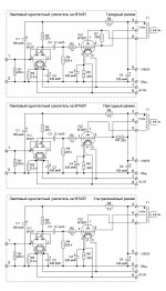
Where there are statistics for el34 in the ultraline mode for a single-ended amplifier.
I mean the optimal mode of operation of the lamp in this mode.
I mean the optimal mode of operation of the lamp in this mode.
Happy to bring it over and let you play with mine as it really is just a nice looking brick right now. Even if you need a little compensation😉
I'd rather see you get it working than take over the project myself, really.
My electronics 'cubbyhole' (closet-sized space) is in the middle of re-organization so probably not a good spot for two of us to look at your amp!
Macbook motherboard and microscope on the bench right now, so different tools...
I'd be happy to drop over with my amp for you to have a listen, and have a look at yours if you are interested in that. Send me a PM here, and we can probably set something up.
BTW, rebuilding into something different could probably involve new components (resistors, caps, wire, terminal lug strips). The good news is that all the real work could be done with a pencil and paper - planning a P2P build is a big part of the whole job.
Where there are statistics for el34 in the ultraline mode for a single-ended amplifier.
I mean the optimal mode of operation of the lamp in this mode.
Please don't be offended if I try to 'interpret' what you have just said:
Do you mean that a circuit using the ultralinear connection on the output transformer will give more power and better results with this tube?
And that the schematic I posted doesn't use the ultralinear connection?
My kit didn't have UL taps on the output transformers, so different than the Boyuu A9 kit.Where there are statistics for el34 in the ultraline mode for a single-ended amplifier.
I mean the optimal mode of operation of the lamp in this mode.
There are lots of options for UL...
Here are some other EL34 SE circuits using ultralinear output transformer taps:
EL34 SE ultralinear schematic
Claus Byrith :
http://www.asinus.dk/Asinus_Elektroakustik/Home_files/cb-amplifier_8wse.pdf
DIY Single-Ended (SE) KT88 / 6L6 / EL34 / 6CA7 Tube Amplifier
asked about the statistics of the mode for el34 for the a9 amplifier
specifically for the el34 lamp in the ultraline mode there are statistics?
specifically for the el34 lamp in the ultraline mode there are statistics?
Last edited:
asked about the statistics of the mode for el34 for the a9 amplifier
specifically for the el34 lamp in the ultraline mode there are statistics?
I don't know if there's really a big difference in performance or output power between using an ultralinear transformer tap and just connecting the screen via a resistor.
It would be interesting to know the difference in the sound of the A9 in the triode, pentode and ultraline modeI don't know if there's really a big difference in performance or output power between using an ultralinear transformer tap and just connecting the screen via a resistor.
Attachments
Just a generalization . . .
Pentodes and Beam Power tubes:
Ultra Linear mode:
A. Has about 2 to 3 times higher plate resistance, rp, versus the same tube triode wired (the damping factor with no negative feed back is only about 1/2 to 1/3 of the same tube triode wired.
B. Has about 2 to 3 times the output power as the same tube triode wired.
C. Requires an Ultra Linear tap on the output transformer, Or requires a much more complicated circuit to simulate the Ultra Linear tap.
D. Requires checking that the Screen maximum voltage is not exceeded with maximum signal.
Triode Wired Pentode and Beam Power tubes:
A. Has about 1/2 to 1/3 of the plate resistance, rp, of the same tube triode wired (the damping factor with no negative feedback is 2 to 3 times better than Ultra Linear.
B. Has about 1/2 to 1/2 of the output power of the same tube in Ultra Linear.
C. Is simple, requires a 100 Ohm Screen stopper resistor.
Pentode wired Pentodes and Beam Power tubes:
A. Has almost no damping if there is no negative feedback.
B. Has about 2 to 3 times the power of the same tube triode wired.
C. Requires a separate voltage to the Screen.
Does that help with the question of Triode wired versus Ultra Linear mode, versus Pentode mode?
Last edited:
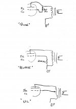
It would be interesting to know the difference in the sound of the A9 in the triode, pentode and ultraline mode
Yes, I agree. It could be done with a switch (switched with power OFF). 🙂
Thanks for those schematics.
I re-drew with a quick sketch - is this correct?
Attachments
Pentode wired Pentodes and Beam Power tubes:
A. Has almost no damping if there is no negative feedback.
B. Has about 2 to 3 times the power of the same tube triode wired.
C. Requires a separate voltage to the Screen.
Does that help with the question of Triode wired versus Ultra Linear mode, versus Pentode mode?
Yes, that does help, thanks.
By 'separate' screen voltage, how 'separate'?
Independent HV secondary winding all the way back at the power transformer, or tapped off the B+ circuit at some point?
Pentode mode:
Be sure to use a well filtered point in the B+ in the multi RC string of the power supplies. Just as you would use extra filtering for a line amp tube or a driver tube than you would for the output tube.
Screens generally like a fairly stiff voltage source.
A. Simple R from B+, and an R to ground. May want to add a bypass capacitor.
Gas regulator tubes are simple, have a plate and a cathode (no filament).
B. Simple R from B+, and one or more Gas regulator tubes in series to ground. Do not use a cap across the regulator tubes.
C. Simple R from B+, and a Gas regulator tubes in series with one or more zener(s) to ground. Do not use a cap across the series string of the zener(s) and regulator tube.
I am experimenting with one of my amps. I use a resistor from B+, to three 39V zener diodes in series, then in series with an 0D3 150V gas regulator tube. I get ~ 270V on the KT66 screen. I use Schade style negative feedback, just a resistor from the KT66 plate to the driver tube plate.
Last edited:
Actually no, wasn't thinking a takeover at all - just a fresh set of knowledgeable eyes and an actual conversation. Waiting a day between questions can be quite frustrating especially if there are context differences between newbie questions and highly technical/baffling (to newbs) responses many of the times. First and foremost the whole point of all this for me is learning. Meanings I am trying to convey do not always translate well in the written word here hence my preference to video/plain talking especially since this A9 thread conversation has 15 simultaneous differing conversations going on at any given time. Many concepts like ultra linear etc are simply above where I am at right now with only a scant few Dr Doug (and others) Youtube videos under my belt. At this stage I Will go with a (mostly) clean strip down and give it another go. This time I will apply a few things I had learned along the way that may make a difference. I have got some good ideas from another participant here in a sidebar email conversation so will go with his ideas (and great images) first and see what that turns up...I'd rather see you get it working than take over the project myself, really.
My electronics 'cubbyhole' (closet-sized space) is in the middle of re-organization so probably not a good spot for two of us to look at your amp!
Macbook motherboard and microscope on the bench right now, so different tools...
I'd be happy to drop over with my amp for you to have a listen, and have a look at yours if you are interested in that. Send me a PM here, and we can probably set something up.
BTW, rebuilding into something different could probably involve new components (resistors, caps, wire, terminal lug strips). The good news is that all the real work could be done with a pencil and paper - planning a P2P build is a big part of the whole job.
Will let you know when I get to the point of another attempt. I am not looking at changing much from the original design at all. I want to get that mostly working good before I even consider straying from the base design (if ever).
Baby steps for me 😉
As an aside I just completed building one of these and it worked straight off the get go - got a great cap discharge unit and a fun assembly out of this project: A Device To Discharge High Voltage Capacitors Safely, Let's Design This. | Mr Carlson's Lab on Patreon

With my upcoming work schedule it may be a couple of weeks before I get it to the point of being ready for a heavy roll to starboard again....
Thanks for the offer.
TMF
Last edited:
I have got some good ideas from another participant here in a sidebar email conversation so will go with his ideas (and great images) first and see what that turns up...
Sounds mysterious!
🙂
Let us know how it turns out!
LongRoad,
Why in post # 732 did they take out the 200 Ohm Screen Grid Stopper Resistor, in the Ultra Linear schematic?
If it is good for Triode mode, and good for Pentode mode, it is probably also a good idea for Ultra Linear mode (200 Ohms between the Ultra Linear tap and the Screen grid).
It also makes it easy to implement, use a single pole 3 way rotary selector switch. Caution: always turn the amp off, and wait for the capacitors to discharge before changing the switch position.
Just a suggestion.
navydiver,
It is nice to have a capacitor discharge unit.
But it seems that so many schematics of the power supply in this thread do Not have any bleeder resistor across the B+. (post # 720 for example)
If you ever forget to use the capacitor discharge unit, and you do not have a bleeder resistor across the B+, you may be surprised (shocked).
Even though all my amplifiers have a bleeder resistor, after I turn off my amp, I always check the B+ with a meter before doing any other probing around, or modifications. Most bleeders do take some time to discharge the caps to a safe voltage. And what if the bleeder resistor fails, or there is a bad connection?
Too low of a bleeder resistance discharges faster, but wastes power, and adds up heat in the amp enclosure.
You should make things as simple as possible, but no simpler - Albert Einstein
- Home
- Amplifiers
- Tubes / Valves
- Boyuu EL34 A9 Tube Amp