looking for100k 3w mini resistors. None to be had.
These are about as small as 3W types will get.
https://www.mouser.com/datasheet/2/351/Xicon_09152016_MO-RC-1201738.pdf
 @gregas - please do not post general trouble-shooting questions in the Sticky thread, your posts and their replies have been moved here.
Gidu
I went to two local electronic shops. None of them had these mini 100k 3watt resistors. Where did you buy from?
Hello !
I bought them on Ebay, but I can not remember the exact address! Try a search on Google with this exact term : 100k 3W PR03 Vishay resistor But beware: the resistors for the grounding of the 6.3 V supply circuits of the filaments are 100 Ohms 3 Watts and not 100k 3 W!
Gidu
Last edited:
Thanks for the help me
Power supply without all lamps = 287v
Power supply without 5z4p = 284v
Voltage under load with all lamps = 280v
5z4p Lamp voltage under load = 4.4v
Without lamp 5z4p = 4.6v
without all lamps = 4.7v
Even so, I think the matter is the insufficient power of the transformer and the inaccurate calculation of the operating voltage on it.
If I'm wrong, correct me please. Thank.

These voltages are actually too low with no load, I think that indeed your power transformer has a problem, although I still say that it was properly dimensioned !
Before changing it by another, check that there are no other problems downstream !
Gidu
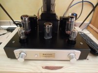
Without load (without lamps) the transformer does not heat up. I bought a transformer in exchange for this. GZbotolave Raphaelite 280W amplifier power transformer EL34,6L6,KT66 push pull tube buffer-in Amplifier from Consumer Electronics on Aliexpress.com | Alibaba Group
There are no other reasons for transformer overheating. I saw that you also cooled the amplifier by placing a fan under it. It is a bad idea to listen to the noise of the propeller.
There are no other reasons for transformer overheating. I saw that you also cooled the amplifier by placing a fan under it. It is a bad idea to listen to the noise of the propeller.
Attachments
Hi !
The Raphaelite transformers seem to be of very good quality !
The fan chosen is an extremely silent fan that normally operates at 12 volts and I voluntarily under-volted at 5 volts DC, which makes it completely inaudible, while refreshing the amp correctly. It increases the longevity of all components, especially capacitors ! And there is no vibration at all ...
Gidu
Last edited:
The fan chosen is an extremely silent fan that normally operates at 12 volts and I voluntarily under-volted at 5 volts DC, which makes it completely inaudible, while refreshing the amp correctly. It increases the longevity of all components, especially capacitors ! And there is no vibration at all ...
Is there no bottom plate (safety cover on bottom of amp) on the Boyuu? And, are there ventilation holes in the top plate of the amplifier? I don't understand how the cooling air passes through the amp. Well-designed low power tube amplifiers (with safety covers) have operated for many years in the past without fans for cooling......using natural convection cooling when necessary.
With all the major heat-dissipating parts -tubes, and in this case, transformers- above the chassis top plate, does the underside of the amp get very hot due to dropping resistors in the power supply , or ????
In the Boyuu A9 amplifier there is a transformer Raphaelite 200W power transformer for 45 2A3 EL34 KT66 single-ended tube AMP DIY 8589944622834 | eBayThe Raphaelite transformers
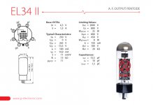
On the power amplifier can give 330v 200ma Maximum current consumption per EL34 lamp 150ma, two lamps need 300ma. The same indicators for the filament of lamps, so the transformer is not stable and is very hot.
Isn't the B+ about 300 volts? (320??) in the A9? Max dissipation of EL34 is about 25 Watts? So isn't the current about 60-70 mA through each tube? (All approximate numbers.....)
The transformer should be able to handle that. If transformers are getting very hot and smoking or melting, I think it's usually a short or low resistance connection to ground in the amp wiring- not just an under-rated transformer. Or the transformer has an internal short? That would make sense of all the reports of A9 amps working OK with the same specification transformer.
The transformer should be able to handle that. If transformers are getting very hot and smoking or melting, I think it's usually a short or low resistance connection to ground in the amp wiring- not just an under-rated transformer. Or the transformer has an internal short? That would make sense of all the reports of A9 amps working OK with the same specification transformer.
I admit the malfunction of the transformer, so I ordered another. The power of the transformer is calculated in developed countries at the maximum possible load. In this case, do not have to put a fan under the amplifier for cooling. For commercial success and in pursuit of profit, the manufacturer deliberately installs a transformer with low power.
Attachments
I believe if you ever have to put a fan underneath an amplifier to keep it safely cool, then you know one of two things:
1. The amp is being used in an environment that is hotter than the maximum rated temperature specification of the amp.
For example an amp that has a maximum temperature rating of 40 Degrees C, but you are using it in a room that is 50 Degrees C.
2. The amp was not designed very well, it is not safe.
I've seen amps that didn't need more cooling because they wren't safe. No bottom plate=Not safe=Better ventilation !
I fully agree with the second paragraph. Temperature conditions are set by the engineer, You can calculate and prevent overheating when creating a basic amplifier circuit. For the environment from -10 * to + 40 * With proper calculations fan is not required.2. The amp was not designed very well, it is not safe.
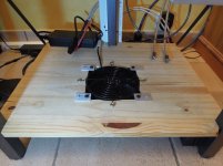
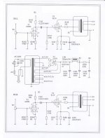
Well folks finally found some time and got the Octal Sockets in plus the circuit board as per the photos (next post). Anybody out there have a 120V schematic as there are significant changes in my unit from the schematics I received (posted on page 44 of this thread)? Colour coding is a bit different for power transformer from the 220V schematic - I believe my input colours are blue and red vs orange and blue. Also I populated the main circuit board which looks completely different from Gidu's pic I re-posted on the same page as above. Both smoothing caps C301 and C303 say they should be 22uF but the ones that came with my kit are 33 uF as per pics (confirmed with seller they did send me a 120V kit and said they would send a 120v schematic by email several days ago - nothing received. Communications is not their strong suit). Here is what I have so far. Anyone have a 120v schematic for the A9?


The amplifier circuit is the same 120 volts and 220 voltsHere is what I have so far. Anyone have a 120v schematic for the A9?
The differences in the transformer.
connect the transformer to the idle and measure the voltage.
Attachments
Colour coding is a bit different for power transformer from the 220V schematic - I believe my input colours are blue and red vs orange and blue.
I wouldn't believe too much - it's only a matter of a few minutes to check the wires to figure out which winding they are connected to.
And as suggested, once you are sure you have the primary wires, connect them to power and see what AC voltages you are getting on the other wires, to make sure your assumptions about colour coding are right. This is before you connect the secondary leads into the circuit.
I use an old AC 'wall wart' adapter which puts out about 20 volts AC instead of the 120v line - useful for testing and lowers the anxiety level.
Have you built a 'dim bulb' tester yet? It will come in handy later.
Also I populated the main circuit board which looks completely different from Gidu's pic
I'd be careful about wiring up the circuit just from pictures.
Also, it looks like a pretty thick coat of paint on that chassis. Make sure the spur washers are cutting through to bare metal when you are bolting components.
Or, sand off the paint at the connection points. A flap wheel in a Dremel is good for this.
As LongRoad said, the amplifier circuit is the same no matter what the primary voltage on the power transformer, assuming they shipped you the 120volt power transformer. You will know that as soon as you check the power transformer voltages. If the heater/filament windings aren't producing the right voltages (3 v instead of 6v, for example) you don't have a 120 v transformer.
It's probably better to refer to the Post #you are referring to.(posted on page 44 of this thread)
You may have 44 pages if you are reading this on a phone or a small screen, or with a low screen resolution and a large font, but on a different computer the number of pages will be different.
(This thread has 10 pages in all on my machine.)
I wouldn't believe too much - it's only a matter of a few minutes to check the wires to figure out which winding they are connected to.
And as suggested, once you are sure you have the primary wires, connect them to power and see what AC voltages you are getting on the other wires, to make sure your assumptions about colour coding are right. This is before you connect the secondary leads into the circuit.
I use an old AC 'wall wart' adapter which puts out about 20 volts AC instead of the 120v line - useful for testing and lowers the anxiety level.
Have you built a 'dim bulb' tester yet? It will come in handy later.
Thank you VG - will build a Dim Bulb tester tomorrow as per: YouTube
Makes perfect sense. I do have a Variac that I use for a DIY Acrylic Bending Machine I built. Thinking I could use that to keep the voltage levels way down??? Yeah, the bending unit is far from the safest electrically - thankfully I am not in full production of these and am super super cautious (famous last words): YouTube
I haven't exposed the leads on the transformers yet as I am waiting for a skookum wire stripper that I just ordered so I don't stress the wires trying to hand bomb it with hand strippers as per: Wire Stripper, EONLION Self-Adjusting Wire Stripping Tool/Cutting Pliers Tool with Wire Stripper/Crimper/Cutter, 8'': Amazon.ca: Tools & Home Improvement
Once I strip the wires I will identify the transformer windings as per Uncle Doug's advice (stumbled onto his excellent channel of tube amp discussions/explanations so am learning loads from his videos): YouTube
Thank you for your patience and guidance
Tim
As LongRoad said, the amplifier circuit is the same no matter what the primary voltage on the power transformer, assuming they shipped you the 120volt power transformer. You will know that as soon as you check the power transformer voltages. If the heater/filament windings aren't producing the right voltages (3 v instead of 6v, for example) you don't have a 120 v transformer.
That is what I had thought but what has got me confused is the fact that the three large caps included with the kit are of completely different values from what is called for on the large PCB I have installed or the 220V schematics thinking I was missing something critical- I was thinking that maybe a 120V schematic would show values that were maybe more appropriate for 60Hz North American operation vs 50Hz Europe etc.
Another DIY that I am building as well. Have parts from Mouser on order to build a Capacitor Discharge device as per: A Device To Discharge High Voltage Capacitors Safely, Let's Design This. | Mr Carlson's Lab on Patreon
Not sure the link is view-able as it is in a Patreon account on Mr Carlsons Labs - another Youtube electronics guy I have been following to siphon knowledge.
Also, it looks like a pretty thick coat of paint on that chassis. Make sure the spur washers are cutting through to bare metal when you are bolting components.
Or, sand off the paint at the connection points. A flap wheel in a Dremel is good for this.
I was actually thinking about that (Paint is quite thick) - of course since there is no build diagram that comes with the unit I have no clue where the critical grounding points are to the chassis to do this are. Are you talking about the banana plug adapters for the 0, 4 and 8 ohm sockets (I don't really see any spur washers in the kit other than on the plugs)? Not sure also where on the chassis I would ground items as shown in the schematics - where I ground these items is not readily obvious to me????
This is why I was hoping to see more pictures to get a feel for the construct - I already know that my PCB board is different than other photos I have seen in this thread which of course means I have to be careful in the build - thinking that dim bulb tester is going to come in super handy😱
It's probably better to refer to the Post #you are referring to.
You may have 44 pages if you are reading this on a phone or a small screen, or with a low screen resolution and a large font, but on a different computer the number of pages will be different.
(This thread has 10 pages in all on my machine.)
Actually I am reading from both (laptop as I type this) and page numbering agrees on this and my Samsung S9+ Android phone - will of course go with post number though in future as I do on other forums like AK etc...
Thanks
Tim
- Home
- Amplifiers
- Tubes / Valves
- Boyuu EL34 A9 Tube Amp