You can check the valve specs sheet, and see that the Boyuu people are rather optimistic about output power rating 😀, and a what kind of THD those 10W are possible... EL34 @ The Valve Museum
..unless you say "hey! this is a stereo unit, hence 8 + 8 watt, this is a 16W amplifier!"
..unless you say "hey! this is a stereo unit, hence 8 + 8 watt, this is a 16W amplifier!"
mmm, I see, maybe some of the kit builders can say if there are ,or not, 6.3V filament UNDER LOAD,See Chart, red indicates actual voltage.
I think you do not understand electrical circuits. Operating voltage should be 315 V. The operating voltage of the incandescent lamp is 6.3 V, pentod 5 V The transformer is wound with a thin wire that does not allow to hold the operating voltage. The voltage drops and the transformer heats up. Thicker wire, they can not use because of the size of the transformer. The Chinese simply fooled with an amplifier "Boyuu A10" put a transformer in it weaker than "Boyuu A9" Make sure it has a transformer 96x60 it's a lie!
Attachments
I think You do not catch my comment, we are two people using a foreing language , it can happen.. I mean, if the Xformer is inadequate and sag under load, You caculate 5.7V instead of 6.3V in one of the secondaries, people that already have the thingy running, can tell if it is so.
You calculate 5.7V instead of 6.3V in one of the secondaries, people that already have the thingy running, can tell if it is so.
Is it a calculation (from theory) or an actual measurement with an AC voltmeter on an operating amp? And A9, or A10?
😕
I apologize for my english 🙄I think You do not catch my comment, we are two people using a foreing language , it can happen.. I mean, if the Xformer is inadequate and sag under load, You caculate 5.7V instead of 6.3V in one of the secondaries, people that already have the thingy running, can tell if it is so.

it is very difficult to find information for you in English, the lowest allowable voltage of the kenotron 5z3 = 4.5 volt
The voltage of the filament and the working voltage can sag a little from the stated, but not so much, there is an obvious constructor oversight.
Attachments

I think you do not understand electrical circuits. Operating voltage should be 315 V. The operating voltage of the incandescent lamp is 6.3 V, pentod 5 V The transformer is wound with a thin wire that does not allow to hold the operating voltage. The voltage drops and the transformer heats up. Thicker wire, they can not use because of the size of the transformer. The Chinese simply fooled with an amplifier "Boyuu A10" put a transformer in it weaker than "Boyuu A9" Make sure it has a transformer 96x60 it's a lie!
Hello !
The Boyuu A09 amp and the A10 do not use the same input tubes: they are 6N9PJ (Octal) on the A09 and 6N2J (Noval) on the A10 !
And the intensity of the heating circuit is not the same on these two tubes: 300 mA under 6.3 Volts on the 6N9PJ and 150 mA under 12 Volts on the 6N2PJ which makes a difference of 300 mA for both 6N2J tubes compared to 6N9PJ, which may explain the respective size difference of the two magnetic circuits that equip the A09 and A10 !
The voltages that you have noted, both the non-rectified HT and the voltages of the two heating coils are obviously abnormal, which, combined with the exothermic heating of the supply transformer, seems to indicate a downstream leakage current that it is necessary to investigate.
I think that first you have to remove all the tubes to check again the no-load voltages: if the voltages return to their normal level (or if they are slightly higher) and that the transformer remains warm (the hand can remain above !) is that the problem does not come from the transformer !
Then, at first, put back in the 5Z4PJ rectifier valve and re-check the voltages: either they go down again and the valve is probably at fault or else the filter capacitors behind (C301, C302, C303 to check !).
Check also the two IN4007 diodes with an ohmmeter !
Either the tensions remain correct and the transformer remains warm and then you put back both EL34 one by one and each time you check the tensions: if they lower by putting one of the two tubes, it is either this tube is bad or the polarization of the latter which is faulty (check R105-205, R107-207, and R108-208), and check also C102-202.
There, we should have progressed well !
And unfortunately, if your power transformer has heated to the point of smoking, it may be necessary to change it anyway, after finding the reason for this overheating, of course!
Do not forget to take all precautions required for your safety, the high voltage on tube amps can be lethal !
Good luck and keep us updated !
Last edited:
Hi Gidu,
If you run with only the rectifier tube, your B+ voltages will all be far too high. There isn't any draw on the B+ to drop the voltage to normal levels. If you have a variac you can reduce the line voltage so you don't damage the filter capacitors. If the filter caps have enough headroom they may be okay to just fire up without the normal tubes installed, but this would be a rare situation. Another trick you can use would be to use a filament transformer wired up to buck the mains voltage. Try a 12.6 V transformer that the secondary can handle the load current of your amplifier. If you wire the buck transformer backwards it will increase the voltage, so check the orientation with all tubes removed first.
Hopefully this trick will let you try to check B+ voltages without anything but the rectifier plugged in. One other caution is that normal voltage drops will not occur, to the B+ voltage for the first stage might be very high. That could damage the lower voltage capacitors downstream. I use a variac which allows me to raise the input voltage enough to get the first stages (lowest voltage) up to operating levels. That means the other B+ voltages will measure low. You could install the signal tubes so that normal voltage drops do occur and that will allow you to run the primary B+ to a normal level with a variac or buck transformer.
-Chris
No! Don't do that!Then, at first, put back in the 5Z4PJ rectifier valve and re-check the voltages: either they go down again and the valve is probably at fault or else the filter capacitors behind (C301, C302, C303 to check !).
If you run with only the rectifier tube, your B+ voltages will all be far too high. There isn't any draw on the B+ to drop the voltage to normal levels. If you have a variac you can reduce the line voltage so you don't damage the filter capacitors. If the filter caps have enough headroom they may be okay to just fire up without the normal tubes installed, but this would be a rare situation. Another trick you can use would be to use a filament transformer wired up to buck the mains voltage. Try a 12.6 V transformer that the secondary can handle the load current of your amplifier. If you wire the buck transformer backwards it will increase the voltage, so check the orientation with all tubes removed first.
Hopefully this trick will let you try to check B+ voltages without anything but the rectifier plugged in. One other caution is that normal voltage drops will not occur, to the B+ voltage for the first stage might be very high. That could damage the lower voltage capacitors downstream. I use a variac which allows me to raise the input voltage enough to get the first stages (lowest voltage) up to operating levels. That means the other B+ voltages will measure low. You could install the signal tubes so that normal voltage drops do occur and that will allow you to run the primary B+ to a normal level with a variac or buck transformer.
-Chris
Gidu
I went to two local electronic shops. None of them had these mini 100k 3watt resistors. Where did you buy from?
I went to two local electronic shops. None of them had these mini 100k 3watt resistors. Where did you buy from?
The voltages that you have noted, both the non-rectified HT and the voltages of the two heating coils are obviously abnormal, which, combined with the exothermic heating of the supply transformer, seems to indicate a downstream leakage current that it is necessary to investigate.
I think that first you have to remove all the tubes to check again the no-load voltages: if the voltages return to their normal level (or if they are slightly higher) and that the transformer remains warm (the hand can remain above !) is that the problem does not come from the transformer
Thanks for the help me

Power supply without all lamps = 287v
Power supply without 5z4p = 284v
Voltage under load with all lamps = 280v
5z4p Lamp voltage under load = 4.4v
Without lamp 5z4p = 4.6v
without all lamps = 4.7v
Even so, I think the matter is the insufficient power of the transformer and the inaccurate calculation of the operating voltage on it.
If I'm wrong, correct me please. Thank.
Attachments
Can anyone explain this? I have a boyuu a9 tube amp. How does one know if grounding the heater wires directly will degrade the sound or damage the tubes/power supplies?Final note on heater lines:
Nor should they be directly grounded to the chassis, unless it is known that they can rest at 0-volts D.C. without degradation of the sound quality or damage to tubes and/or power supplies.
Can anyone explain this? I have a boyuu a9 tube amp. How does one know if grounding the heater wires directly will degrade the sound or damage the tubes/power supplies?
Blanket general statement that may or may not apply to any given circuit. I don't know the context in which that statement was made. Was nazaroo referring to heater-to-cathode voltage limitations? A cathode follower, for instance, can have its cathode lifted +150V or more above ground. If you supply that cathode follower with a heater supply that is grounded to 0V, then the cathode of the tube will be at a constant +150V above the heater. Since most tubes have a maximum DC heater-cathode voltage limit of 100V, that would be well over the limit, and could cause premature failure of the tube.
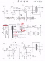
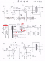
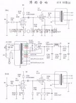
Looking at Boyuu A9 schematic:
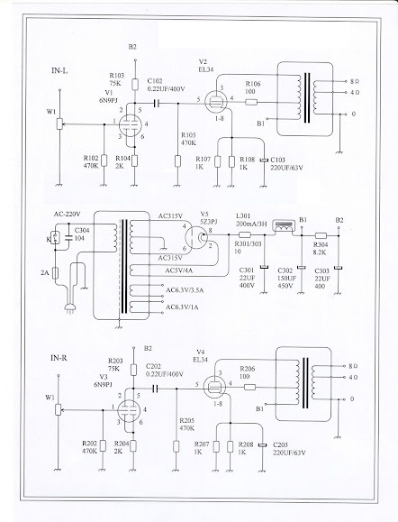
There is no cathode follower in that circuit, so that's not an issue. The EL34 is cathode biased, so its cathode may sit as high as +35V above ground. That's well within the 100V max heater-cathode limit, so no problem there if the heater supply is referenced to 0V ('ground'). The 6SL7 is also cathode biased, and probably has its cathode sitting at about +1.5V above ground. That again is not a problem.
So in that circuit, referencing the heater supply to ground should not be a problem.
Is that what you were asking?
--
Edit to add:
The power supply diagram does not show how the heater supplies are grounded. Of course they need to be grounded. AC heater supplies should not be left floating.
Also, there should be grid stoppers on the tubes. There are none indicated in the diagram.
Who makes that amp?
Last edited:
rongon,
Thanks for the response. I'm new to tubes and this is way over my head. I think you've answered my question. I just want to make sure i can connect the heater wires to ground without damaging anything. The reason is to stop hum. On the boyuu a9 thread people are using 2- 100k 3w resistors and grounding each wire from the 6n9pj tube and 2 more resistors of the same value for the el34 tube. Would there be any difference in tone or audio quality if i ground directly vs grounding through resistors?
Thanks for the response. I'm new to tubes and this is way over my head. I think you've answered my question. I just want to make sure i can connect the heater wires to ground without damaging anything. The reason is to stop hum. On the boyuu a9 thread people are using 2- 100k 3w resistors and grounding each wire from the 6n9pj tube and 2 more resistors of the same value for the el34 tube. Would there be any difference in tone or audio quality if i ground directly vs grounding through resistors?
Grounding is a tricky one to grasp, and I'm far from an expert. I think the term itself is misleading as it implies a link to a 0v reference must be present. Quite often heater circuits will be referenced to an elevated voltage and not 0v. I often use the 6X5GT rectifier tube and routinely link pins 7 and 8, tying the heaters to the cathode and thus avoiding a common problem with that tube, namely exceeding the heater-cathode difference. Of course havign done that there must be no other reference voltage.
I've also seen references to benefits from raising the heater above the cathode. Worth reading and researching.
The Valve Wizard has a very good grounding article (chapter from his book) available for free download and I'd heartily recommend this very well written piece.
The Valve Wizard
Is it necessary for a heater circuit to have a reference of some sort ? Yes I think (someone will step up and correct me perhaps). But it certainly shouldn't always be 0v.
Last edited:
rongon,
Thanks for the response. I'm new to tubes and this is way over my head. I think you've answered my question. I just want to make sure i can connect the heater wires to ground without damaging anything.
You can't connect an AC heater supply (6.3V secondary from a power transformer) directly to ground. That will short the winding to ground and (hopefully) blow the fuse that protects the transformer. Are you sure you mean "connect the heater wires to ground"? The heater wires should be connected to the heaters, so that they heat the cathodes, and electrons flow through the tube.
On the boyuu a9 thread people are using 2- 100k 3w resistors and grounding each wire from the 6n9pj tube
Exactly which pins on the 6N9P tube?
and 2 more resistors of the same value for the el34 tube.
Again, exactly which pins on the EL34 tube?
Would there be any difference in tone or audio quality if i ground directly vs grounding through resistors?
You bet there would be! If you connect the heater windings directly to ground there will be no sound at all.
The Boyuu A9 schematic is not instructive. I highly recommend reading that chapter from Merlin Blencowe on grounding. Merlin's books are really good. Worth purchasing, for absolute sure.
Merlin Blencowe's Books and Publications Spotlight
--
Have a look at the attached schematic. It shows the simplest type of heater wiring for two tubes (an EL34 and a 6SL7) using a 6.3V AC secondary with a center-tap. (The schematic is stolen from Merlin's Valve Wizard site and then doctored for this purpose. I hope he doesn't mind.) Notice that the transformer secondary winding is center-tapped, and that center tap is grounded. That means there is 3.15V AC on either side of the center tap, which together makes 6.3V AC across the entire secondary winding.
--
Attachments
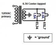
Last edited:
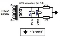
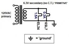
Attached to this message is a schematic of the same heater supply as in the previous post, but now using a heater secondary winding that has no center tap.
Note to where the ground symbol has been moved.
It is critical that the heater supply is grounded in one place only.
Note to where the ground symbol has been moved.
It is critical that the heater supply is grounded in one place only.
Attachments
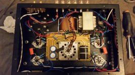
I've uploaded a picture of my a9 showing the wiring. On the 6n9pj tube the heater wires go terminal 7 and 8. I have a blue wire going from pin 7 to ground on the board. On the El34 they go on pin 2 and 7. i have a white wire going from pin 7 to ground on the board. The amp plays this way.
Attachments
Thanks. I understand. What you're doing is this (in the attached schematic labelled 'PRIMITIVE').
Yes, that will work.
It is not the best way to wire an AC heater supply.
Adding resistors to that type of circuit will do little to nothing to reduce noise from the heaters.
The better way is with two resistors connecting from either end of the secondary winding to ground, creating a resistive center tap for the primary winding. Merlin B calls this an "Artificial Centre Tap":
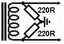
I got that from Merlin's excellent page on Heater Supplies. The page is written for people who want to design tube (valve) guitar amps, but the concepts for a hi-fi power amp are exactly the same.
The Valve Wizard
Read that, and you should come away with a much better idea of what's going on in your Boyuu amp.
--
Yes, that will work.
It is not the best way to wire an AC heater supply.
Adding resistors to that type of circuit will do little to nothing to reduce noise from the heaters.
The better way is with two resistors connecting from either end of the secondary winding to ground, creating a resistive center tap for the primary winding. Merlin B calls this an "Artificial Centre Tap":
I got that from Merlin's excellent page on Heater Supplies. The page is written for people who want to design tube (valve) guitar amps, but the concepts for a hi-fi power amp are exactly the same.
The Valve Wizard
Read that, and you should come away with a much better idea of what's going on in your Boyuu amp.
--
Attachments

Thanks for the tips i will definitely check out the valve wizard.
I plan on trying a set up with resistors. I went to 2 local electronic shops
looking for100k 3w mini resistors. None to be had. Even looking on line seems proving to be difficult. Any idea for a source?
I plan on trying a set up with resistors. I went to 2 local electronic shops
looking for100k 3w mini resistors. None to be had. Even looking on line seems proving to be difficult. Any idea for a source?
- Home
- Amplifiers
- Tubes / Valves
- Boyuu EL34 A9 Tube Amp