LongRoad
Thank you for the response. I'll let the tubes burn in further.
Does adding a grid resistor of 3.3 kilo ohm on 6N9PJ tubes have any effect on the tone? I have not done this yet
Greg
Thank you for the response. I'll let the tubes burn in further.
Does adding a grid resistor of 3.3 kilo ohm on 6N9PJ tubes have any effect on the tone? I have not done this yet
Greg
Grounding heater to circuit board.
Hey Guys. What are the advantages or disadvantages of using a resistor or not using a resistor when grounding the wires for the heater.
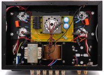
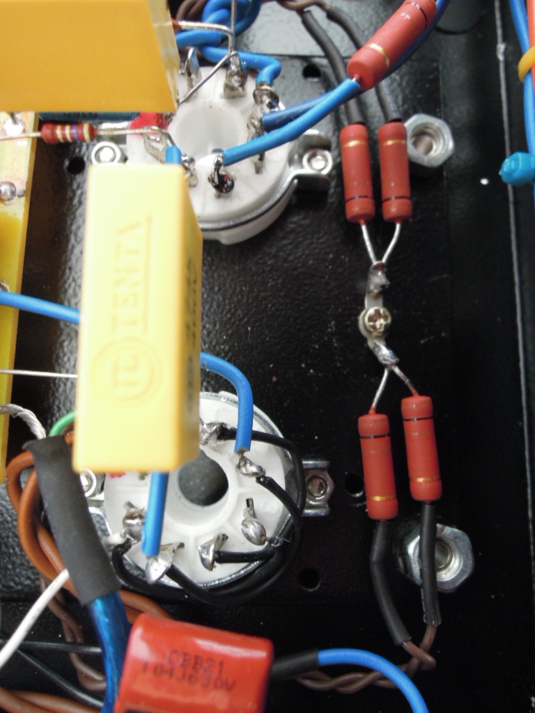
I've followed the wiring in this picture. It looks like there is no resistor used when grounding the heater wires for both the power tubes and the rectifier tubes. I had a problem with hum that got a lot better when i grounded the heater wire as shown in the picture.
Hey Guys. What are the advantages or disadvantages of using a resistor or not using a resistor when grounding the wires for the heater.
I've followed the wiring in this picture. It looks like there is no resistor used when grounding the heater wires for both the power tubes and the rectifier tubes. I had a problem with hum that got a lot better when i grounded the heater wire as shown in the picture.
Attachments
Grounding heater to circuit board.
Hi Greg
It reduces hum from imbalance of filament windings.
Preben
Hi Greg
It reduces hum from imbalance of filament windings.
Preben
i grounded the heater wire as shown in the picture.

Need to do strictly according to the amplifier circuit.
see post Boyuu EL34 A9 Tube Amp
enjoy ��
Boyuu began to produce defective transformers, Look at the voltage measurements of factory finished product A10.Ah OK ! The heating of the power transformer also often depends on the mains voltage : at home, it does not exceed 230 Volts. But, in Russia, with a 220 Volts sector, the transformer should not overheat normally, unless frequent surges !
Despite this, I noticed that at certain times of the day, the amplifier, as well as the other components of my system, were more or less hot: I think that it comes from the variations of the tensions of the sector and the temperature of the room !
You will see to control the mains voltage !
The transformer overheats and starts to smoke after 2 hours of music.
Attachments

LongRoad,
What does having music playing on the amplifier have to do with heating and burnout? The schematic in post 425 shows a 2 channel class A single ended amp.
A Class A single ended amp does not draw more current from the power transformer when music is being played, versus when music is not being played. * * * The exception is: if you turn the music volume up all the way, and the amp is clipping all the time. Many of us do not listen to our amplifiers at levels that are constantly clipping.
If the power transformer is defective, it will burn itself up after 2 hours, with or without music being played at moderate levels.
The amplifier circuit for my boyuu was not very good and not complete. My question is why use a resistor at all? in the image that i provided the heater circuit is grounded directly to the circuit board ground without a resistor. Is it a bad idea?Need to do strictly according to the amplifier circuit.
see post https://www.diyaudio.com/forums/tubes-valves/268969-boyuu-el34-a9-tube-amp-32.html#post5285494
enjoy ��
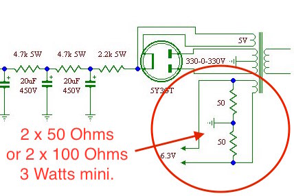
Do Not ground the heater wires for the rectifier tube. It is at B+ volts.
For the 6.3V 3.5 Amp, and the 6.3V 1 Amp secondaries, use 4 each 100 Ohm resistors. Ground Each of the 4 secondary leads through a 100 Ohm resistor. That will tend to reduce any hum that is caused by the filament to cathode interface.
Be sure that the 6.3V 3.5 Amp secondary is powering the 2 EL34 output tubes (3 Amps). The 6.3V 1 Amp winding is for the input tubes. Connecting the 1 Amp secondary to the 2 EL34 tubes will cause the transformer to heat and/or smoke.
Last edited:
6A3sUMMER
Thanks for the explanation. Is there any difference if I ground to the circuit board or to the chassis? Also I see some people are using a resistor on the signal wire coming from the pot. Is it strictly used to reduce hum or does it have an effect on the tone?
Thanks for the explanation. Is there any difference if I ground to the circuit board or to the chassis? Also I see some people are using a resistor on the signal wire coming from the pot. Is it strictly used to reduce hum or does it have an effect on the tone?
gregas,
All of my amps are wired point to point (none of them are Boyuu amps).
My RCA phono jack inputs are insulated from the chassis. The RCA jack ground connects to the bottom (0) end of the volume control; and from there it connects to the bottom ('ground', 0) end of the parallel RC self bias network of the input tube. From there, the RC bias network connects to the central ground of the amp.
The central ground point has many wires coming to it, and it is connected to the chassis (the only connection to the chassis, except for the ground of the 3 wire IEC power socket, which connects to the chassis directly at that socket).
The output transformer secondary Common tap also connects to the central ground of the amp.
All the other points in the amp that need to return to ground are connected to the central ground point, with these exceptions: The high voltage secondary center tap, the first B+ filter cap minus, and the second B+ filter cap minus.
The HV center tap connects directly to the first B+ filter cap minus terminal, then a wire from there connects to the second B+ filter cap minus terminal, and another wire from the second B+ filter cap minus terminal connects to the central ground. That prevents the B+ ground loops from being introduced into the rest of the amp's grounding scheme.
I mechanically align the Output Transformer laminations at right angles to both the power transformer, and the B+ choke. And I use lots of space from the output transformer to the power transformer and choke. I use aluminum chassis, not magnetic steel.
Attention to detail, plus experience fixing hum issues has allowed most of my amps to have less than 100uV hum at the output. (I use indirect heated tubes, do not use negative feedback, and do not have to regulate the power supplies). I no longer use DHTs.
Last edited:
All
Well folks - here I is - another toob noob from Victoria, BC jumping into the foray! Here is what I got me today and will likely need some help along the way. Link to Youtube vid here: YouTube
Imagery shows the documentation I received and one image I found on the ePray ad to start the build with - wholly lacking in the instructions department I have to say! Lots of questions will follow shortly. My first is regarding the orientation of pin 1 in the final product assembly diagram. Is there a standard for where the pin one should be oriented to the case because from the photo shown it is hard to judge whether the layout in the schematic is being followed in the one low res photo I have to go by - Doh! Also the little daughter boards are enough to drive me nuts - thought these things were supposed to be point to point wired. Without board layout diagrams it is hard to judge orientation of the boards vs schematic intent. Oh Christmas is going to be fun this year😱😀😕🙄😱


From my ePray ad - only thing I have to go by wrt where some of the bits go....

Well folks - here I is - another toob noob from Victoria, BC jumping into the foray! Here is what I got me today and will likely need some help along the way. Link to Youtube vid here: YouTube
Imagery shows the documentation I received and one image I found on the ePray ad to start the build with - wholly lacking in the instructions department I have to say! Lots of questions will follow shortly. My first is regarding the orientation of pin 1 in the final product assembly diagram. Is there a standard for where the pin one should be oriented to the case because from the photo shown it is hard to judge whether the layout in the schematic is being followed in the one low res photo I have to go by - Doh! Also the little daughter boards are enough to drive me nuts - thought these things were supposed to be point to point wired. Without board layout diagrams it is hard to judge orientation of the boards vs schematic intent. Oh Christmas is going to be fun this year😱😀😕🙄😱
From my ePray ad - only thing I have to go by wrt where some of the bits go....
Last edited:
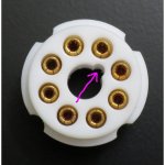
Looking at this image I found herein I am seeing where this fellow has red marks on the white tube mount hardware (for lack of a better term). Is this how pin 1 is identified? I note that one on the top right has two red marks on it just to make it confusing. The one in the middle has none. Hmmmmm
Thank you for any guidance on this first of many questions. Of course I will be looking at pin assignments on the sketchy schematics but want to do what is right by convention if there is one.
Thanks
Tim
😕🙂

Thank you for any guidance on this first of many questions. Of course I will be looking at pin assignments on the sketchy schematics but want to do what is right by convention if there is one.
Thanks
Tim
😕🙂
Last edited:
You count, clockwise, from the key slot. Those red marks are on pins 2 & 7, which are the heater.
You count, clockwise, from the key slot. Those red marks are on pins 2 & 7, which are the heater.
Yup! What Eli says... And always 'looking at' the bottom of the tube. You are lucky to have a photo guide, which is something more than completely starting from scratch. Remember to get the tube socket orientation correct when bolting them to the chassis. It makes a difference to the wiring layout- keeping leads short is almost always better.
A lot of work with pencil and paper can save headaches. Print out copies of the schematic and use a highlighter to mark the connections you have made. Wire (especially modern wire with easy-to-melt insulation) and components don't generally take well to solder-unsolder-re-connect cycles.
Looking at this image I found herein I am seeing where this fellow has red marks on the white tube mount hardware (for lack of a better term). Is this how pin 1 is identified? I note that one on the top right has two red marks on it just to make it confusing. The one in the middle has none. Hmmmmm
Thank you for any guidance on this first of many questions. Of course I will be looking at pin assignments on the sketchy schematics but want to do what is right by convention if there is one.
Thanks
Tim
😕🙂
View attachment 720254
Hi !
I'm the guy who cabled the amp on this picture !
The red dots you see on the tube supports correspond to the connections for the heaters (6,3 V) of the tubes !
And don't forget to add these resistors :
For the 6.3V 3.5 Amp, and the 6.3V 1 Amp secondaries, use 4 each 100 Ohm resistors. Ground Each of the 4 secondary leads through a 100 Ohm resistor. That will tend to reduce any hum that is caused by the filament to cathode interface.
Gidu
Last edited:
Boyuu began to produce defective transformers, Look at the voltage measurements of factory finished product A10.
The transformer overheats and starts to smoke after 2 hours of music.
Hi !
As 6A3Summer says, I think you probably reversed the filament feeds of the EL34 (3 Amps) and the input tubes (1 A), which explains why the power transformer is overheating !
Gidu
Hi ! I'm the guy who cabled the amp on this picture !
Thank you for the feedback Gidu but I'm afraid I am in need of baby steps. Your diagram looks nothing like what I received - intent was to build as received then do mods to fix issues afterwards (no doubt I will have to - part of my learning process). I am a bit perplexed in that it looks like the schematic I received (posted above) is for a 220V AC power supply whereas I reside in Canada at 120V 60 Hz - they even confirmed I wanted this voltage in an email before sending the kit based on my location. Now it appears that I will have to verify the installed transformer because of their obvious lack of attention to detail.....
Also all the cap values I received are different from what is in the schematics. They must have good drugs over there in China😕
You count, clockwise, from the key slot. Those red marks are on pins 2 & 7, which are the heater.
Thank you Eli - I am still a bit confused. By the looks of it the ceramic tube holder thingys I received look to have 4 key slots. As near as I can tell I see no difference looking down on the top of the holder that differentiates one slot from another. On the bottom there are four grooves at the cardinal points that can hold the metal chummy that is used to bolt it to the case. Will give it a best guess and install with pin 1 oriented at the approximate 1 o'clock position towards the transformer side of the case.
Cheers
Tim
😕
Tim:
Those 8-pin sockets are called 'octal' tube sockets.
Online searching can save you a lot of time and frustration.
As I mentioned in the other thread ("another Newbie...."), you can contact me if you want 'local help'.
Checking transformer windings is 'all part of the fun' - it will come in handy when you find a salvaged transformer some day. Trusting the irregular colour system used for wires on these transformers is a gamble, no matter how many pictures you find of finished amps.
Do you have a multimeter? Use the continuity setting to identify windings for a start, then use a low voltage AC source connected to the primary and figure out what each winding output voltage will be.
It's a hobby activity, right? 🙂
If you could just wire up the amp in an evening, where would the fun be in that?😀
Those 8-pin sockets are called 'octal' tube sockets.
Online searching can save you a lot of time and frustration.
Thank you for the feedback Gidu but I'm afraid I am in need of baby steps. .......😕
As I mentioned in the other thread ("another Newbie...."), you can contact me if you want 'local help'.
Checking transformer windings is 'all part of the fun' - it will come in handy when you find a salvaged transformer some day. Trusting the irregular colour system used for wires on these transformers is a gamble, no matter how many pictures you find of finished amps.
Do you have a multimeter? Use the continuity setting to identify windings for a start, then use a low voltage AC source connected to the primary and figure out what each winding output voltage will be.
It's a hobby activity, right? 🙂
If you could just wire up the amp in an evening, where would the fun be in that?😀
Attachments
Thank you, but I bought the finished amplifier and did not change anything in it.Hi !
As 6A3Summer says, I think you probably reversed the filament feeds of the EL34 (3 Amps) and the input tubes (1 A), which explains why the power transformer is overheating.
Gidu
In the amplifier "Boyuu A10" there is a transformer 96x50 instead of 96x60 which is indicated in the advertising prospectus.
This is eliminated only by replacing the transformer, which can provide the necessary operation mode of the amplifier.
Explain to me please
Declared amplifier output power:
Boyuu A10 12w Power transformer 96x50
Boyuu A9 10w Power transformer 96x60
What scientists calculated the rated power of these amplifiers?
If the formula for calculating the transformer power over the cross section of the core is known to all.
How the transformer will work and produce the required supply voltage if it is overloaded and not intended for the required power.
Attachments

- Home
- Amplifiers
- Tubes / Valves
- Boyuu EL34 A9 Tube Amp