omni protector
Dear Sir
greetings please can you show
1 where is acessory input to be connected
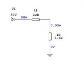
2 since transformer is 50 0 50 there is no 7 volt ac tapping how to use the 2 resistors to get 7 volts ac and please their VALUES
hoping you can please help me
warm regards
andrew lebon
Dear Sir
greetings please can you show
1 where is acessory input to be connected
2 since transformer is 50 0 50 there is no 7 volt ac tapping how to use the 2 resistors to get 7 volts ac and please their VALUES
hoping you can please help me
warm regards
andrew lebon
Wind on a dozen or more extra turns to get your 5Vac to 7Vac and create your isolated 7Vdc from there.
dear Victor
greetings please can you tell value of 2 resistors to get 7 volts ac
from 50 volts ac transformer post 425
warm regards
andrew lebon
How is clipping figure ?
does this amp design have symmetrical clipping ?
omni protector
hi Nmos
greetings omni protector will be used with my h class amp main goal is to
1 cut off speakers if speaker impedance is below 2 ohms most h class amps can do it provided output transistors are rugged amp has been tested on 2 ohms
2 short circuit protection very important
3 clipping circuit will be there havent tested it clipping very important for amp
warm regards
andrew lebon
Hi andrewlebon
im confused......
what is omni protector ?
class h with quasi or Dr. Bora mosfet amp ?
or Do you mean Apex H900 class H amp ?
can you email me schematic padiscount@yahoo.com
Dear Sir
greetings please can you show
1 where is acessory input to be connected
2 since transformer is 50 0 50 there is no 7 volt ac tapping how to use the 2 resistors to get 7 volts ac and please their VALUES
hoping you can please help me
warm regards
andrew lebon
Hi Andrewlebon
Maybe something like this...or put 50V AC instead od 7AV but increase resistor 1K with let's say 39K...
Attachments
whats omni
im confused......
what is omni protector ?
class h with quasi or Dr. Bora mosfet amp ?
or Do you mean Apex H900 class H amp ?
hi Nmos
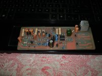
greetings OMNI is a DC protector for amplifiers it has
1 short circuit protection
2 turn on delay
3 cuts off speaker line if speaker impedance is below 2 ohms this can be set
can be used with most amplifiers
warm regards
andrew lebon
im confused......
what is omni protector ?
class h with quasi or Dr. Bora mosfet amp ?
or Do you mean Apex H900 class H amp ?
hi Nmos
greetings OMNI is a DC protector for amplifiers it has
1 short circuit protection
2 turn on delay
3 cuts off speaker line if speaker impedance is below 2 ohms this can be set
can be used with most amplifiers
warm regards
andrew lebon
The Omni information was posted by Dr Bora starting here -
http://www.diyaudio.com/forums/soli...egrated-247-output-devices-28.html#post649777
I think Ostripper posted a single zip with all info towards the end of this page -
http://www.diyaudio.com/forums/soli...amp-pcb-integrated-247-output-devices-31.html
http://www.diyaudio.com/forums/soli...egrated-247-output-devices-28.html#post649777
I think Ostripper posted a single zip with all info towards the end of this page -
http://www.diyaudio.com/forums/soli...amp-pcb-integrated-247-output-devices-31.html
omni protector
Dear Dr BORA
greetings please can you help me out want to find out how resistance to voltage regulator LM7824 is calculated and wattage of resistance
1 my supply voltage 72 volts dc positive negative
2 RELAY VOLTAGE 12 VOLT
3 relay coil resistance 160 ohms
warm regards
andrew lebon
Dear Dr BORA
greetings please can you help me out want to find out how resistance to voltage regulator LM7824 is calculated and wattage of resistance
1 my supply voltage 72 volts dc positive negative
2 RELAY VOLTAGE 12 VOLT
3 relay coil resistance 160 ohms
warm regards
andrew lebon
Attachments
Andrew, this is older version with 24V regulator for relays supply and it wasn’t reliable. Please make a small modification and replace that with simple one transistor stabilizer as on attached schematic. I know PCB isn’t designed for this, but modification is so simple it shouldn’t be a problem to do.
Attachments
thank you SIR
Dear DR BORA
greetings thank you sir for replying its easy modification i will make it thanks once again for helping me
warm regards
andrew lebon
Dear DR BORA
greetings thank you sir for replying its easy modification i will make it thanks once again for helping me
warm regards
andrew lebon
Andrew, this is older version with 24V regulator for relays supply and it wasn’t reliable. Please make a small modification and replace that with simple one transistor stabilizer as on attached schematic. I know PCB isn’t designed for this, but modification is so simple it shouldn’t be a problem to do.
Hi boraomega
Im confused and have a problem....
how to connect Omni protection Point 7 and 9
in quasi complementary output stage
like Legend Stage master MK2 or Quasi NMOS
because Point 7 and 9 get full negative rail voltage trough 0,22 OHM resistor
any solutions ?
Attachments
OMNI is for complementary outputs and not for quasicomplementary. Quasi output stage has to be modified.
OMNI is for complementary outputs and not for quasicomplementary. Quasi output stage has to be modified.
I dont have much experienece how to modifed for Quasi output stage,
can you share your knowldege / offer schematic what to do for Quasi
cheers
omni protector
, this is older version with 24V regulator for relays supply and it wasn’t reliable. Please make a small modification and replace that with simple one transistor stabilizer as on attached schematic. I know PCB isn’t designed for this, but modification is so simple it shouldn’t be a problem to do.
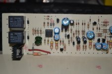
just remove ic 7824 the 2 10uf caps and the jumper to modify pcb for transistor stabilizer put TIP 41 WHERE 7824 was orignally
1 put 24 volt zener diode from base of tip41 to where jumper was taken out to ground
3 put 3.3k 1 watt from collector to base
no tracks to be cut PCB has all holes marked on it
warm regards
andrew lebon
, this is older version with 24V regulator for relays supply and it wasn’t reliable. Please make a small modification and replace that with simple one transistor stabilizer as on attached schematic. I know PCB isn’t designed for this, but modification is so simple it shouldn’t be a problem to do.
just remove ic 7824 the 2 10uf caps and the jumper to modify pcb for transistor stabilizer put TIP 41 WHERE 7824 was orignally
1 put 24 volt zener diode from base of tip41 to where jumper was taken out to ground
3 put 3.3k 1 watt from collector to base
no tracks to be cut PCB has all holes marked on it
warm regards
andrew lebon
ok thanks for Info....will make new PCB, its easy for me but need a little time
if interested I can share it for supplier
I hope to get update for Omni to protect Quasi output stage
Hi Dr. Bora and everybody! I'm new in forum.
I've read this topic, from page 1 to here. I'm interested in building the Sigma & Techno amps. They look seem similar topology, only difference is between BJT and MOSFET in OPS. My computer does not CAD program to draw the PCB. Someone please send to me the PCBs of both (top & bottom)?!
Somebody can help me?
Top & bottom PCB layout of Techno & Sigma. (Send to my email: Nguyenthecuong1987@gmail dot com)
Very thanks for help me!!! 🙂
Dear Dr.Bora
I'm completing the purpose of spare parts on the stage driver amplifier Sigma
2SA1407/2SC3601 or 2SA1406/2SC3600 the Sanyo brand. BJT brands like this are hard to find in my town. Is there a replacement series of other brands such as the brand Sanken, Toshiba or other brands. Thank you
Good Luck,
A.Pramudia
Dear Dr. Bora,
Your e-mail about BJT I've read, your response so quickly. Thanks a lot
Good luck,
A.Pramudia
Your e-mail about BJT I've read, your response so quickly. Thanks a lot
Good luck,
A.Pramudia
- Home
- Amplifiers
- Solid State
- Bora is a nice guy from Serbia - Yugoslávia