HELLO
Dear Dr Bora
greetings after a long time i decided to test omni dc protector
delay on is working dc protection is working using 40 040 ac torridal 1KVA
i have 7 volts ac on it after checking delay and dc protection is working ok
i decided to check if omni cuts off if load is below 2 ohms and if i short speakers while amp is playing if trafo is in series with 100 watt bulb short and low impedance cut off is working very good but on giving direct ac 220 volts
short and low impedance is not working please can you tell me whats wrong i tested protector on 2 pair ab class amp 55 volts dc +/- my amp
in ab class has 12 pairs and my dc supply will be 70 volts dc +/- please can you help me i really need this short circuit and low impedance protector
warm regards
andrew lebon
Attachments

Hi andrewlebon,
Low impedance detector will sense if speakers are of lower impedance than preset value or if speaker cable is shorted, but it will do that ONLY in a short period before speaker relay switch the speakers on. After that, this sensor can not sense what is happening with speakers or cables, but there you have overload protection which will react on excessive current through output devices.
You have everything explained in this attached text.
Attachments
Greets to Dr. Bora,
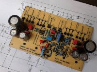
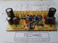
as i'm writing this i hear music played by monoblock of your great Modus aka Technno Amp.
set bias to 25mv, temperature on HS 39-40C, dc offsett 5,6 mV, supply 40Vdc 😎
Thanks for this great Amp.
regards
naf
as i'm writing this i hear music played by monoblock of your great Modus aka Technno Amp.
set bias to 25mv, temperature on HS 39-40C, dc offsett 5,6 mV, supply 40Vdc 😎
Thanks for this great Amp.
regards
naf
Attachments
-
 20120506_173659_rsz.jpg84.8 KB · Views: 806
 -
 20120506_144202_rsz.jpg103.5 KB · Views: 859
 -
 20120506_143816_rsz.jpg109.6 KB · Views: 879
 -
 20120428_183410_rsz.jpg110.1 KB · Views: 313
 -
 20120429_124137_rsz.jpg105.8 KB · Views: 285
 -
 20120429_124720_rsz.jpg94 KB · Views: 261
 -
 20120506_114228_rsz.jpg81.5 KB · Views: 251
congrats bro!, nice buildMy Modus Ampfilier...still testing. I am waiting for silver mica caps on boards...
Excelent work naf and Arif! Designer is always happy to hear such impression from DIY builders!
in links under my posts-
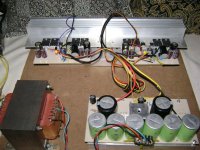
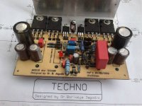
Now here are some pictures for FB albums! 🙂
Greets to Dr. Bora,
as i'm writing this i hear music played by monoblock of your great Modus aka Technno Amp.
set bias to 25mv, temperature on HS 39-40C, dc offsett 5,6 mV, supply 40Vdc 😎
Thanks for this great Amp.
regards
naf
Now here are some pictures for FB albums! 🙂
Dear DR. Bora,
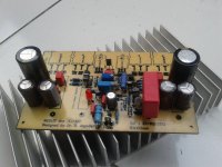
My Modus Amp is having 15mV bias setting, 40 Vdc supply. I use fan blower to help its cooling. The sound is very clear, tight and kicked low. I like to play fussion jazz, Rock and Heavy metal songs. Some traditional music songs also (Keroncong) playing by Modus Amp. I plan to raise the bias up to 25 if it possible.
But the problem is my EI transformer, only 5A (the best I could find on my city) for feeding both channels (in Indonesia ampere scale is written on every transformer by manufacturer, not watt). It will be hot after more or less 2 hour playing CD. The bridge diode also has the same case. I guess it might be lack of transformer capability, I order bigger customized toroidal transformer to replace my 5A one, but I have not received it yet. Some local diy friends told me their bad experience buying some toroidal transformers, they burnt out after playing 2 or 3 songs. It is hard to find the good quality toroidal transformers here, since I am living in the small city. To get the good quality toroidal transformers is only by internet order, but the shipping cost is very expensive, almost the same with its price, then I have to pay one good quality toroidal transformer at double price...he he he.
Some friends who like the sound of my Modus Amp and need to have it, are suggested to contact MR. Bora directly by me. But they have some problem with English.
Thank you so much Dear DR. Bora for giving me the very good design, and all personal emails, since I know that DR. Bora is very busy.
Best Regards,
Arif B
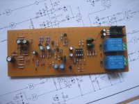
My Omni protect build...it's a good thing I did a check on the thread for I have not known that the regulator has been modified...this project was done a year ago but never been finished and tested...guess I will be able to complete it by now....😀
Attachments
Dear DR. Bora,
My Modus Amp is having 15mV bias setting, 40 Vdc supply. I use fan blower to help its cooling. The sound is very clear, tight and kicked low. I like to play fussion jazz, Rock and Heavy metal songs. Some traditional music songs also (Keroncong) playing by Modus Amp. I plan to raise the bias up to 25 if it possible.
.................................................................................................
Some friends who like the sound of my Modus Amp and need to have it, are suggested to contact MR. Bora directly by me. But they have some problem with English.
Thank you so much Dear DR. Bora for giving me the very good design, and all personal emails, since I know that DR. Bora is very busy.
Best Regards,
Arif B
I am not sure,but i beleive that bias for MODUS-TECHNO is about 100mA. Not sure but not far away...

Naf,
post704.
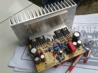
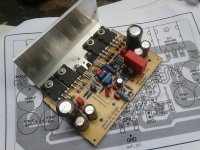
the output devices are mounted on the inside of the L angle aluminium bracket.
It is extremely difficult to ensure a flat face here for the devices to contact for good Thermal Conductance (low Thermal Resistance).
If the PCB and output devices are turned upside down then the devices contact the outside face of the L. This face can be checked and altered to ensure it has a goof flat surface for good heat flow.
A further advantage of using the outside face it that the devices can be mounted much closer to the heatsink. Maybe as much as 8mm closer. That reduces the Thermal Resistance considerably. This helps the output stage to run less hot and more reliably.
post704.
the output devices are mounted on the inside of the L angle aluminium bracket.
It is extremely difficult to ensure a flat face here for the devices to contact for good Thermal Conductance (low Thermal Resistance).
If the PCB and output devices are turned upside down then the devices contact the outside face of the L. This face can be checked and altered to ensure it has a goof flat surface for good heat flow.
A further advantage of using the outside face it that the devices can be mounted much closer to the heatsink. Maybe as much as 8mm closer. That reduces the Thermal Resistance considerably. This helps the output stage to run less hot and more reliably.
Or using a heatsink where the flange is part of the casting/extrusion and not a bolted on L bracket.
Yes, I know. I have four of them.
As far as I can tell they are sand cast. I doubt die casting would ever be economic, unless they took over the entire world production of these style of heatsinks.
Sand casting would also explain why the backs/flanges are machined. Another extra cost.
As far as I can tell they are sand cast. I doubt die casting would ever be economic, unless they took over the entire world production of these style of heatsinks.
Sand casting would also explain why the backs/flanges are machined. Another extra cost.
Last edited:
I am not sure,but i beleive that bias for MODUS-TECHNO is about 100mA. Not sure but not far away...
Modus bias setting is about 100mA up to 120 mA, but my Heatsink is too small...When I set 100mA (22mV across R 0,22 Ohm) all final transistor were hot, so I think it is better to set bias at 15mV until I get the proper Heat Sink.
Best Regards,
Arif
AndrewT thanks for your suggestion i will considering it when i've finished my second monoblock.Naf,
post704.
the output devices are mounted on the inside of the L angle aluminium bracket.
It is extremely difficult to ensure a flat face here for the devices to contact for good Thermal Conductance (low Thermal Resistance).
If the PCB and output devices are turned upside down then the devices contact the outside face of the L. This face can be checked and altered to ensure it has a goof flat surface for good heat flow.
A further advantage of using the outside face it that the devices can be mounted much closer to the heatsink. Maybe as much as 8mm closer. That reduces the Thermal Resistance considerably. This helps the output stage to run less hot and more reliably.
Modus bias setting is about 100mA up to 120 mA, but my Heatsink is too small...When I set 100mA (22mV across R 0,22 Ohm) all final transistor were hot, so I think it is better to set bias at 15mV until I get the proper Heat Sink.
Best Regards,
Arif
Sorry,didn´t considered that...
- Home
- Amplifiers
- Solid State
- Bora is a nice guy from Serbia - Yugoslávia