Yes relay is 10A. I understand your diagram. Thanks a lot for the help. Can you tell me about the interconnection thing?
Regards
Regards
It's better to use 16A relay... Just worried for the relay of 10A ,not to stick contacts!
Now we have to solve the cross connection...
I apologize for the bad picture but I really did not have time to do better.
Pins 6,7,8,9 are free, they should not be linked because they have no purpose for such construction

Now we have to solve the cross connection...
I apologize for the bad picture but I really did not have time to do better.
Pins 6,7,8,9 are free, they should not be linked because they have no purpose for such construction
No Problem I am trying to understand it I will make refine diagram and post here. you just double check it I will post it later today. Thank you very much for the help
Regards
Regards
No, the LED goes exactly according to the scheme, the anode goes to +24 V and the cathode to pin 12, pin 11 not used.
Another thing, CT transformer goes to the ground by the power of the electrolyte and also minus the speakers and then the one common point GND
You do not have to use a transformer for AC voltage of 7V, using two resistors with existing tranformer 2 * 50V AC get 7V AC.
Another thing, CT transformer goes to the ground by the power of the electrolyte and also minus the speakers and then the one common point GND
You do not have to use a transformer for AC voltage of 7V, using two resistors with existing tranformer 2 * 50V AC get 7V AC.
Omni
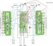
Hi I just have redraw the interconnection diagram please just double check it.
I would like to ask one thing; In this configuration when I turn on the amp will both of the supplies will turn on silently?
should I use Two separate supplies for separate channels or one big supply for both the channels?
Currently I am using 40,000uf + 40,000uf capacitance bank for two separate channels is it fine?
Just advice me on that. I want my supplies to turn on silently.
Regards
Attachments
You did not connect well, see the corrected image
How do you think that the power supply include silent? Have you thought of "tump" in speakers? At inclusion, a few seconds after the relay will include silent speaker.
Please read this, http://bas.elitesecurity.org/OMNI-english.doc
You need soft start for power supply.
An externally hosted image should be here but it was not working when we last tested it.
How do you think that the power supply include silent? Have you thought of "tump" in speakers? At inclusion, a few seconds after the relay will include silent speaker.
Please read this, http://bas.elitesecurity.org/OMNI-english.doc
You need soft start for power supply.
Hi Viktor1986,
I understand now. I have read the Omni English text also. Let me finish it then I will tell you the result. My friend I really appreciate your help and support.
Regards
I understand now. I have read the Omni English text also. Let me finish it then I will tell you the result. My friend I really appreciate your help and support.
Regards
changing from 10A rating to 16A rating may make little to no difference in the risk of contacts sticking/welding/arc not extinguishing.It's better to use 16A relay... Just worried for the relay of 10A ,not to stick contacts!
The DC rating for breaking a continuous fault current is a very onerous specification.
You may, maybe should, take other steps to ensure the relay stands a real chance of breaking a DC fault current when you expect it to do so.
Opening the speaker feed AND shorting the fault current to ground improves the situation.
Fitting supply rails fuses that are close rated helps.
Fitting an input mute helps when it is the input signal that is generating the fault current.
Rail crowbars are another option to consider.
Last edited:
Hi Viktor,
It is working LED is on now. Thanks a lot. Now I have to put all in a case and then see the result.
Regards
It is working LED is on now. Thanks a lot. Now I have to put all in a case and then see the result.
Regards
Do you changed the value of the 56K resistor? What is the new value of 47K ... 33K?
Send us a picture
Send us a picture
Smps
Hi Viktor1986,
I want to make an SMPS from 220VAC to +/- 70VDc. Could you please direct me to some thread where I could find information on that?
Regards
Do you changed the value of the 56K resistor? What is the new value of 47K ... 33K?
Send us a picture
Hi Viktor1986,
I want to make an SMPS from 220VAC to +/- 70VDc. Could you please direct me to some thread where I could find information on that?
Regards
Hi Viktor1986,
I want to make an SMPS from 220VAC to +/- 70VDc. Could you please direct me to some thread where I could find information on that?
Regards
I have not followed the themes related to smps, once I was heated for one project, it's K6 smps, but I gave up then although I have complete documentation. http://www.a-and-t-labs.com/K6_Sw_Amp/index.htm
http://www.diyaudio.com/forums/showthread.php?t=149702
I found this on Google, http://www.coldamp.com/opencms/opencms/coldamp/en/products/power_supplies/SPS80HV/index.html
http://84.255.231.51:81/index.php?page=hb_prot2
Hi Viktor,
My friend I have found this on Dr Bora's website. It looks very nice. I was only thinking about that how can I use it with 230VAC to +/- 70 VDC. because This SMPS is originally designed for car audio I mean from 12VDC to +/-70 VDC. What do you say about it?
http://bas.elitesecurity.org/mojiprojekti1.html
Regards
This is DC/DC SMPS! You need AC/DC SMPS!
This is DC/DC SMPS! You need AC/DC SMPS!
yes I need Ac to DC SMPS
Legend stage master
Hi Dear`Vicktor,
Yesterday, I have finished my Legend Stage Master. It's working and sound quality is very good. I just want to know one thing I biased the amp to 45ma to 50ma total Is it fine or I must bias it to 100ma total (25ma per Fets pair)? and will 100ma effect amplifier's performance?
Regards
This is DC/DC SMPS! You need AC/DC SMPS!
Hi Dear`Vicktor,
Yesterday, I have finished my Legend Stage Master. It's working and sound quality is very good. I just want to know one thing I biased the amp to 45ma to 50ma total Is it fine or I must bias it to 100ma total (25ma per Fets pair)? and will 100ma effect amplifier's performance?
Regards
- Home
- Amplifiers
- Solid State
- Bora is a nice guy from Serbia - Yugoslávia