Pretty much depends on the input pair transistors you use and overall topology.
Degeneration works as a local feedback.
The higher the value - the lower gain of the input stage, higher local linearity, better local phase responce, but the global loop gain is also lower, leading to higher overal stability.
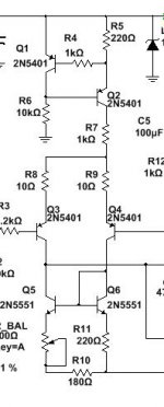
2N5401 is a relatively low-hFE, so the low value of those resistors is safe enough.
If the input pair would use some BC560 or BC556, for example, I would use 100R or so, as a starting point.
The value strongly influences the overall gain / phase responses and stability margins or the amplifier, so I don't recommend to change it without checking those in simulation, to avoid surprises.
Degeneration works as a local feedback.
The higher the value - the lower gain of the input stage, higher local linearity, better local phase responce, but the global loop gain is also lower, leading to higher overal stability.
2N5401 is a relatively low-hFE, so the low value of those resistors is safe enough.
If the input pair would use some BC560 or BC556, for example, I would use 100R or so, as a starting point.
The value strongly influences the overall gain / phase responses and stability margins or the amplifier, so I don't recommend to change it without checking those in simulation, to avoid surprises.
Pretty much depends on the input pair transistors you use and overall topology.
Degeneration works as a local feedback.
The higher the value - the lower gain of the input stage, higher local linearity, better local phase responce, but the global loop gain is also lower, leading to higher overal stability.
2N5401 is a relatively low-hFE, so the low value of those resistors is safe enough.
If the input pair would use some BC560 or BC556, for example, I would use 100R or so, as a starting point.
The value strongly influences the overall gain / phase responses and stability margins or the amplifier, so I don't recommend to change it without checking those in simulation, to avoid surprises.
350ns shift at 40khz. I'm measuring where the input vs. output cross zero.
This number does not give us too much information - you need to look at the global feedback loop AC analysis curves - the most interesting part will be around ULGF - somewhere just above 1-2MHz.
That's where you can possibly ruin the stability, up to stable oscillation.
That's where you can possibly ruin the stability, up to stable oscillation.
Bode plot of the closed loop system reflects potential issues, but in order to see what exactly is going on and assess the stability margins (phase margin and gain margin), you need to look "inside the loop".
Here is a brief description of one of the ways how to do it:
Negative Feedback, Part 9: Breaking the Loop
The other way, used by many people here, is the Tyan probe method - you can find related examples in LTSpice.
Here is a brief description of one of the ways how to do it:
Negative Feedback, Part 9: Breaking the Loop
The other way, used by many people here, is the Tyan probe method - you can find related examples in LTSpice.
Well this is odd. Measuring across the emitter resistors shows nothing yet turning up the bias clearly shows a change in current draw off my power supply.
nvm. wrong emitter. I soldered the test wires to both emitters of the same rail. 🙄
Now I need to figure out why my bias is 500mv across a 0.22r resistor. 😱
Now I need to figure out why my bias is 500mv across a 0.22r resistor. 😱
Can't get the bias below 110ma even if I remove R19 completely. With R19 in place, bias was over 2a. Went over the PCB a dozen times and can not find an error.
Ignore the measurements in the emulator. They are not reflecting real-world measurements at the moment.
Ignore the measurements in the emulator. They are not reflecting real-world measurements at the moment.
Attachments
Do you have an oscilloscope connected to the output?
Such a high bias measurement with no R19, means - most likely HF oscillation is there.
Such a high bias measurement with no R19, means - most likely HF oscillation is there.
I'll scope the output and see if there's anything there. If I short C to E of the VBE, the output should turn completely off shouldn't it?
No oscillation. Heck of a lot of noise in my power supplies though. I may have to break out the variac and make a linear bipolar supply.
I'll scope the output and see if there's anything there. If I short C to E of the VBE, the output should turn completely off shouldn't it?
Yes, shorted bias spreader has to result in zero quiescent current.
I recommend to always have an oscilloscope connected to the output, especially when you're testing some new design / build. This way, you're always aware of what's going on at the output, being able to react before things go completely wild (not always possible, but still may save some parts from burning.
I'm lost now. I have no idea why the bias is wrong. I verified the layout a dozen times and checked all resistor values with the DMM. Cap polarity is correct and everything is in the right place. Maybe the emulator model for the BD139G is wrong.
Yes. I have ~25mv across an emitter resistor with R19 removed and if I jump C to E of the bias servo I still have ~25mv. So about 113ma idle current.
Yes. I have ~25mv across an emitter resistor with R19 removed and if I jump C to E of the bias servo I still have ~25mv. So about 113ma idle current.
That means - something is wrong. Some wrong pinout, bad driver - whatever.
With the the servo C-E jumpered and no load you have to see zero voltage over the emitter resistors.
You have to find the issue before moving further.
Here the update on this. Hopefully it makes sense.
First off, the offset issue I have (only 10s of mv) is the trimmer not providing enough adjustment to compensate for device tolerance. I can swap in 10 different 5401s and wind up with 10 different results. I'm changing both trimmers to 220r. The resistors in series with the trimmers will be reduced so trimmer center is balanced and go from there.
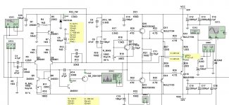
Now here's the bias issue. I'm using a BD139G for the VBE. In the emulator, all values were centered around the BD139G model in Multisim. The BD139G in the real world was different, giving me just over 2a (AMPS) of idle current. I increased the value of the real world resistor that's in series with the bias trimmer to get the current down to an acceptable level of about 50ma.
For ***** and giggles I went back to Multisim and only swapped the BD139G to a BD139 and low and behold I'm showing just over 2a of idle current in the emulator. To get the emulated current back down, I swapped the trimmer series resistor to the value I had to swap in the real circuit. It produced the same results with current back down to 50ma in the emulator like it was in the real circuit.
Bottom line, the BD139 and BD139G don't act quite the same in the emulator but may act the same in the real world.
Does anyone see any issue with my using a TO92 device as my VBE? Would the 2n5551 be suitable to use there?
First off, the offset issue I have (only 10s of mv) is the trimmer not providing enough adjustment to compensate for device tolerance. I can swap in 10 different 5401s and wind up with 10 different results. I'm changing both trimmers to 220r. The resistors in series with the trimmers will be reduced so trimmer center is balanced and go from there.
Now here's the bias issue. I'm using a BD139G for the VBE. In the emulator, all values were centered around the BD139G model in Multisim. The BD139G in the real world was different, giving me just over 2a (AMPS) of idle current. I increased the value of the real world resistor that's in series with the bias trimmer to get the current down to an acceptable level of about 50ma.
For ***** and giggles I went back to Multisim and only swapped the BD139G to a BD139 and low and behold I'm showing just over 2a of idle current in the emulator. To get the emulated current back down, I swapped the trimmer series resistor to the value I had to swap in the real circuit. It produced the same results with current back down to 50ma in the emulator like it was in the real circuit.
Bottom line, the BD139 and BD139G don't act quite the same in the emulator but may act the same in the real world.
Does anyone see any issue with my using a TO92 device as my VBE? Would the 2n5551 be suitable to use there?
Last edited:
- Status
- Not open for further replies.
- Home
- Amplifiers
- Solid State
- Bootstrapped amps. DX/Aksa/RCA/etc...