
Use a real current mirror, i.e. replace D3 by another KSC1815. Perhaps it may help.
Best regards!
Best regards!
Maybe also reduce a little the value of mirror degeneration resistors.
About Bode plot, normally I look for a smooth phase and amplitude without sharp transitions. Your is good but a margin to perfect it exists, since is good to have a spare for compensating the real amplifier assembly (a too fast amplifier or one with sharp phase rotations is difficult to stabilyze in practice).
A cautious fellow (cautious? who, me? 😉🙂 ) build it with higher compensating capacitors and reduce step-by-step until the simulation values, watching if quiescent current don't change with it (a sign of oscillations). Sometimes is impossible to use the simulated values.
Most times I started with simulation values and needed to increase it to avoid oscillations.

Albert,
I have not analysed thoroughly, but if I read your graph (post #198) correctly, the test signal is 50 KHz, the 'bother' around 3µS duration.
Why should that be a problem in audio? You are not designing an instrumentation amplifier ....
(Technically the problem is 'running out of steam' as suggested, for which more current is required somewhere. Still, as asked?)
Albert,
I have not analysed thoroughly, but if I read your graph (post #198) correctly, the test signal is 50 KHz, the 'bother' around 3µS duration.
Why should that be a problem in audio? You are not designing an instrumentation amplifier ....
(Technically the problem is 'running out of steam' as suggested, for which more current is required somewhere. Still, as asked?)
Hi Johan,
I see your point, post #198 is a test run to see if changes will reflect in the resulting graphs. I strip it down to a simpler circuit making sure that I am not going in circles simulating the same circuit while expecting different results because the same graph is shown with my previous attempts. [my first and logicians]
I am not familiar with the topology, my knowledge was that this design runs on lower currents. I am actually following the reference voltages per the original schematic [posted earlier] . My doubts also goes to a low LTP [0.800ma/leg] and VAS [a little over 5ma] currents but my attempts of increasing them results to totally high dc offset 100-200mv. The newer mod seemed to correct a few problems [hopefully] but dc offset is still high at 17mv. By experience, to get a low dc offset in an actual build, it had to be in uv level at least in simulation.
Sa muli,
Albert
the degen resistor on Q8 is zero ohms. Try a selection from 5r to 50r and see how they affect simulated performance.
Try changing the collector load on Q7. start at 500r and go up doubling in value till you reach 4k. See how they affect performance.
Add input LTP degeneration resistors. try from 25r to 400r. See how they affect performance.
You will need to adjust the input LTP current to restore the LF open loop gain back to a chosen value for each change. Otherwise you are comparing a different amplifier before and after a change.
Andrew,
You hit it spot on! Applying a small resistor at Q8 and a few values adjustment at Q7 degen + adding 180r LTP degen, and I got what I was looking for, a uv level dc offset!
@Logician, sorry pal I omitted your LTP degen mod I didn't realize that it is one of the components that was needed . 😱
@Kay, pairing the LTP current mirror as both transistor could also work but degen needs adjusting to a very high value.
@DIYBras, the lump at closed loop gain can be flatten by increasing C1 and per your accounts I would be very cautious also, increasing may lose high freq details 😉
Sa muli,
Albert
Attachments

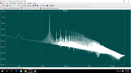
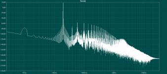
By the way the IMD graph at post#201 is wrong this is the correct one ['sorry about that]....just thought I could show it to you because I know some are very good at this. [I'm not one of them for sure 🙂] They see right thru the intermodulated signal against the fundamental harmonics the even/odd harmonics.
I'm used to seeing the usual 2 tone IMD test in Microcap but just as I'm about to learn the Tian probe in Microcap I found an erratic behaviour between the two simware. Microcap claims the .lib files of LTSpice as its own and LTSpice claims the .cir files of Microcap [similarly build spice algorithm?]. The result is bad 'cause both simware crashes with no apparent reason while simulating. I had to uninstall the other one 🙁
@lazzer408, sorry for the long post...just thought I could pitch-in in your bootstrap amp thread...similar subject and no intention of threadjacking. PM me if im doing it wrong and I will pull out. 😉🙂
Sa muli,
Albert
I'm used to seeing the usual 2 tone IMD test in Microcap but just as I'm about to learn the Tian probe in Microcap I found an erratic behaviour between the two simware. Microcap claims the .lib files of LTSpice as its own and LTSpice claims the .cir files of Microcap [similarly build spice algorithm?]. The result is bad 'cause both simware crashes with no apparent reason while simulating.
I had to uninstall the other one 🙁@lazzer408, sorry for the long post...just thought I could pitch-in in your bootstrap amp thread...similar subject and no intention of threadjacking. PM me if im doing it wrong and I will pull out. 😉🙂
Sa muli,
Albert
Attachments
Elektor EQUIN is one of rather few well thought bootstrap amps. It didn't make it in the DIJ scene because of many "forged" 2N3050 were around. It doesn't work well with much faster power amps, too.
Hi hahfran,
That was considered, the Aurex design operates on low currents driving low beta and low ft output devices. Maestro Damir [dadod] has already cautioned me. The turning point would be, keep the same design and use the same slower devices, or transform the circuit to drive modern devices. In this part of the world, most of the older and obsolete devices can still be found but the risk is to determine which one's are the genuine from the counterfeit.
Sa muli,
Albert
Elektor EQUIN is one of rather few well thought bootstrap amps. It didn't make it in the DIJ scene because of many "forged" 2N3050 were around. It doesn't work well with much faster power amps, too.
Can you point me to a pdf file on this amp?
Thanks!
Can you point me to a pdf file on this amp?
Thanks!
Found it, it was an amp code named "Edwin 20 watts" amplifier😉
On a side note,
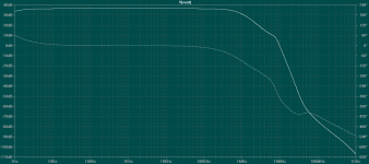
Guys, I will put a hold on my Aurex mod work , while doing simulation in calculating phase and gain margin I got these figures..
OLG = 64.45dB
ULGF = 314.79KHz
-96° - (-180°) = 84° PM
GM =5dB
Not really some better figures, I may have to do more work with it.
Thank you for all your help,
Sa muli,
Albert
Found it, it was an amp code named "Edwin 20 watts" amplifier😉
There was also a 40 watts version, quasi complementary, with a pair of 2N3055's as output devices. Smart detail: It uses the output 'lytic as bootstrapping capacitor!
Best regards!

Hello,
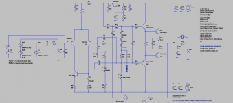
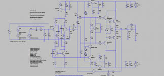
Continuing with my work, here is my revised design. The schematic was based on a few ideas from the Memory distortion papers, another idea from an Ultra Fidelity amplifier design found in the net, and from an image of a bootstrap with a cascode VAS posted by member gaetan. From what I gather bootstrap sounds best if used with a cap multiplier. The cascode VAS is used to mitigate possible parasitic influences from the input stage.
I am still having problems with clipping though as the negative swing clips earlier than the positive swing. I have tried an additional buffer to the cascode, it increased OLG but PM and GM does not seem to improve. I would like to try cascoding the cascode to see the effect but I do not know how to do that. From what I gather it also works with good results.
Simulated results;
CLG = 36dB
OLG = 45.42dB
ULGF = 896.69KHz
PM = 84°
GM = 12dB
Any more help and thoughts in the design is very much apprecited.
Sa muli,
Alber
Attachments

I am surprised that your CLG and OLP are so close.
They indicate that your amp has ~ 9dB of feedback at the lower frequencies.
At what frequency does that feedback start to roll off?
The compound input quad is running Q1&2 @ ~2mA and Q4&5 @ ~1mA.
From what I remember it's more usual to run 4&5 at higher current than 1&2.
What happens to operation if you change those currents? Try equal and then try swapping.
I am finding it difficult to read your pic.
Can you attach a slightly bigger version, maybe 800 pixels vert, or even 1000 vert if it helps readability.
Last edited:
I am surprised that your CLG and OLP are so close.
They indicate that your amp has ~ 9dB of feedback at the lower frequencies.
At what frequency does that feedback start to roll off?
1KHz
The compound input quad is running Q1&2 @ ~2mA and Q4&5 @ ~1mA.
From what I remember it's more usual to run 4&5 at higher current than 1&2.
What happens to operation if you change those currents? Try equal and then try swapping.
I am finding it difficult to read your pic.
Can you attach a slightly bigger version, maybe 800 pixels vert, or even 1000 vert if it helps readability.
Haven't tried swapping currents of the input quad. Q4 & Q5 seems to be sensitive in gain. I ll see if I can make a pdf copy of schematic.
- Status
- Not open for further replies.
- Home
- Amplifiers
- Solid State
- Bootstrapped amps. DX/Aksa/RCA/etc...