Imagine an IC having the pins numbered backwards but the pin definitions are correct in the datasheet.
There used to be some MiniCircuits devices in DIP-outline-compatible packages with very "creative" pin numbering. I forget which anymore, but it caused a few board re-layouts that I know of.
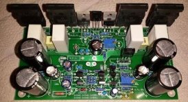
Looking good! Always a good feeling when the boards arrive and the first one is finished and ready for testing.
Why not treat us with a high resolution image and schematic!
Why not treat us with a high resolution image and schematic!
Thanks. It's nothing to special though. A bootstrapped amplifier but with CCS, LTP, and CM (current mirror) on the front end. Buffered VAS. Cdom and Cbypass are 47pf. Cbypass is supposed to be 10p but I can't find the bag of 10p capacitors.
So far so good. It plays. I had a ~20mv+ offset issue that turned out to be my mistake of putting a 100r resistor where a 180r should be. The \ through the 0 in the PCB software makes it look like an 8. Couldn't have been 188 so it must have been 100, right? Nope. Was 180. 🙂 Offset now 0.5mv but I'm sure it'll drift around. The adjustment range is good though. I need a good way to measure idle current. Maybe 1r in series with one of the rails?
I don't have a THD analyzer but I can get some scope pics soon.
Thanks. It's nothing to special though. A bootstrapped amplifier but with CCS, LTP, and CM (current mirror) on the front end. Buffered VAS. Cdom and Cbypass are 47pf. Cbypass is supposed to be 10p but I can't find the bag of 10p capacitors.
So far so good. It plays. I had a ~20mv+ offset issue that turned out to be my mistake of putting a 100r resistor where a 180r should be. The \ through the 0 in the PCB software makes it look like an 8. Couldn't have been 188 so it must have been 100, right? Nope. Was 180. 🙂 Offset now 0.5mv but I'm sure it'll drift around. The adjustment range is good though. I need a good way to measure idle current. Maybe 1r in series with one of the rails?
I don't have a THD analyzer but I can get some scope pics soon.
You've got an emitter resistor for each output device - just measure the voltage drop over them (with no signal) and divide by the resistor value - that will be a quiescent current through a single output pair - just what you need.
You've got an emitter resistor for each output device - just measure the voltage drop over them (with no signal) and divide by the resistor value - that will be a quiescent current through a single output pair - just what you need.
You mean current through a single device right?
You mean current through a single device right?
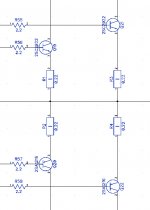
You can measure each resistor one by one, however, you will get more precision if you measure across the pairs - R1 + R2 and / or R3 + R4 (see attached example).
Then, divide the voltage by the total resistance (0.44R for the example here).
It will give you the quiescent current through a single pair.
We assume that you've got zero offset at the output.
It's better to measure with no load connected.
Attachments
You can measure each resistor one by one, however, you will get more precision if you measure across the pairs - R1 + R2 and / or R3 + R4 (see attached example).
Then, divide the voltage by the total resistance (0.44R for the example here).
It will give you the quiescent current through a single pair.
We assume that you've got zero offset at the output.
It's better to measure with no load connected.
Ok I see what you mean now. So just probe a pair of output emitters? Offset can be adjusted to 0v. I'm really happy with how well that adjustment is working.
Ok I see what you mean now. So just probe a pair of output emitters? Offset can be adjusted to 0v. I'm really happy with how well that adjustment is working.
Yes, exactly - just measure the voltage between the emitters.
Some mV offset will not affect your voltage measurement (so, "close to zero" is ok), especially with no load connected.
Member
Joined 2009
Paid Member
"just probe a pair of output emitters".... oh how many times have I blown something up when the probes slip... 😀
"just probe a pair of output emitters".... oh how many times have I blown something up when the probes slip... 😀
Been there,done that! It happened to me while adjusting the bias and one of my kids jumped off his bunk bed to the floor above my head!
Cheers
I even started making special holes on PCB for that purpose - in case we don't have a plug in place for current sensing, which is also very good for preventing the probes slipping 😉
alligator to banana test lead,never can slip😉Been there,done that! It happened to me while adjusting the bias and one of my kids jumped off his bunk bed to the floor above my head!
Cheers
No,
Bad alligator 🙂 too easy to short something out, with exposed metal.
I meant
http://ca.mouser.com/ProductDetail/...=sGAEpiMZZMs4AFwHyzhTm5l9RkZanDRIREAvVYO4CLc=
OR
http://ca.mouser.com/ProductDetail/...=sGAEpiMZZMs4AFwHyzhTm97H2KT2mt3USbjP34urCvU=
I just make my own, using the parts, as the Pomona pre-assembled stuff is expensive.
No,
Bad alligator 🙂 too easy to short something out, with exposed metal.
I meant
http://ca.mouser.com/ProductDetail/...=sGAEpiMZZMs4AFwHyzhTm5l9RkZanDRIREAvVYO4CLc=
OR
http://ca.mouser.com/ProductDetail/...=sGAEpiMZZMs4AFwHyzhTm97H2KT2mt3USbjP34urCvU=
I just make my own, using the parts, as the Pomona pre-assembled stuff is expensive.
That's the right clip to use. Or solder a lead to the device pad or even the device lead itself if necessary.
Member
Joined 2009
Paid Member
Bigun,
Did you learn and buy/make some proper lead clips to banana plugs for your DMM?
I have found myself being to lazy - I have resorted to using these little cheapo wires with little crocodile clips on each end, I think I got a few off ePay sometime ago. I put crocodiles onto the circuit and the other ends onto the DMM probes. Seems to work ok.
.... oh how many times have I blown something up when the probes slip... 😀
Seems to work ok.
Until the many times it didn't. 😀
- Status
- Not open for further replies.
- Home
- Amplifiers
- Solid State
- Bootstrapped amps. DX/Aksa/RCA/etc...