Tolu said:Thanks,
is gain 4x too much? Should I try x1 (as buffer)?
4x is probably too much if you're mainly using a cd player. Try between 1 and 2x. I'm also messing with a simple preamp right now. 1x will not be best, apparently op-amps are no good as buffers, plus it will possibly oscillate.
Simon
Ryssen said:
It´s the best I´ve heard,when is the dream one comming?

Hehe, maybe it will never come! I've just removed the 4562s in my cd player's output stage to make way for a discrete stage and it really is leagues ahead. But the 4562 was the closest in sound to the discrete output.
Simon
A quick question for you learned gentlemen. I was about to replace the LF353 chips in my Marschand crossover with Burr-Brown OPA2134 units.
In your opinion, would the 4562 be a better choice?
Thanks for your thoughts,
Pete
In your opinion, would the 4562 be a better choice?
Thanks for your thoughts,
Pete
SimontY said:
Hehe, maybe it will never come! I've just removed the 4562s in my cd player's output stage to make way for a discrete stage and it really is leagues ahead. But the 4562 was the closest in sound to the discrete output.
Simon
Hi Simon
What kind of discrete circuit did you use
Can you show us the schematic ?
thanks
Legarem
Hi folks,
burned down the right channel of my Alps Motorpot because I plugged my opamp the wrong way (1=8). Sh..! 23€ away.
When I grounded the input section I got noise on the speakers which I had not before (without the ground). What went wrong?
I think I have to pause until I get a new Alps.
burned down the right channel of my Alps Motorpot because I plugged my opamp the wrong way (1=8). Sh..! 23€ away.
When I grounded the input section I got noise on the speakers which I had not before (without the ground). What went wrong?
I think I have to pause until I get a new Alps.
Peter Menting said:A quick question for you learned gentlemen. I was about to replace the LF353 chips in my Marschand crossover with Burr-Brown OPA2134 units.
In your opinion, would the 4562 be a better choice?
Thanks for your thoughts,
Pete
It depends what characteristics are important to you. The 2134 sounds fairly nice, the 4562 sounds accurate. The 2134 is a safe bet and the 4562 seems to be a matter of taste (becuase it's so clean yet, at times, without the musical communication).
Simon
legarem said:Hi Simon
What kind of discrete circuit did you use
Can you show us the schematic ?
thanks
Legarem
Hi Legarem,
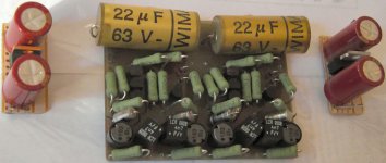
It was designed by Ray/6h5c of this monster thread http://www.diyaudio.com/forums/showthread.php?s=&threadid=54009&perpage=10&pagenumber=1 (700+ pages!)
It's class a and uses FETs. It also has the passive filter onboard. I used decent parts - Kiwame 2w resistors, polystyrene caps, Elna Cerafine psu caps. Blows even the 4562 away...by making every cd sound enjoyable! It always finds the best in a recording, as well as showing what's wrong, but in a benign way.
I can't find the schematic right now, sorry.

Simon
Attachments
Simon;
The nice part about these devices is their price. Think I'll try both and go from there.
Pete
The nice part about these devices is their price. Think I'll try both and go from there.
Pete
Peter Menting said:Simon;
The nice part about these devices is their price. Think I'll try both and go from there.
Pete
Agreed, and that's a good idea. I'm using 2134 and 2132 in my preamp right now. They sound decent enough!
Simon
Route the lines from the mains socket along the edge of the cabinet -- don't let them dangle in space.
If you have RFI you'll need to bypass the power supply rails of the opamps with 100nF ceramics. You could also place a 220pF mica cap across the input lines of the preamp, ferrite bead on the input to the opamp, etc.
If you have RFI you'll need to bypass the power supply rails of the opamps with 100nF ceramics. You could also place a 220pF mica cap across the input lines of the preamp, ferrite bead on the input to the opamp, etc.
Here's a few.
- Make the path between the opamps and the pot a LOT shorter.
- Close the lid of the enclosure (with the front in metal mounted).
Just to make sure that the interference is comming from the curcuit. Try to short the input and listen, is the broadcast still there now ?
- Make the path between the opamps and the pot a LOT shorter.
- Close the lid of the enclosure (with the front in metal mounted).
Just to make sure that the interference is comming from the curcuit. Try to short the input and listen, is the broadcast still there now ?
Sounds great!!
Hi
after I got a new Alps pot, I soldered it directly on the preamp pcb. That worked. Now the sound is perfect. Rich heights and mids, well controlled bass. And no noise or strange radio stations.
Thomas
Hi
after I got a new Alps pot, I soldered it directly on the preamp pcb. That worked. Now the sound is perfect. Rich heights and mids, well controlled bass. And no noise or strange radio stations.
Thomas
Measurable effects of passive components
Looking for measurements of the audible effects introduced by passive components I've came across some interesting page:
http://www.maxim-ic.com/appnotes.cfm/an_pk/3171
It's obvious that capacitors introduce some kind of distortion, since the formula I=C(dV/dT) would apply only for a perfectly linear dielectric, which can't exist since polarization happens due to a finite set of electrons changing within a discrete set of states, but it's the first time I've seen some plots of distortion vs capacitor type and frequency.
Does somebody know if these results are serious/repeatable?
Cyril Bateman did a very comprehensive review of capacitor distortion in EW several years back -- and of course, there is the Jung Marsh paper which was published in Audio circa 1980 -- WJ has it on his website as Audio is defunct.
Nice articles, thanks.
Why are so many posts in the diy community arguing that passive components have no measurable effect on the sound or that they have no effect at all?
Why are so many posts in the diy community arguing that passive components have no measurable effect on the sound or that they have no effect at all?
ionomolo said:Why are so many posts in the diy community arguing that passive components have no measurable effect on the sound or that they have no effect at all?
Probably because the effects of non-ideal behaviour of passive components (resistors and capacitors) are largely swamped by non-linearity and noise of active components like transistors, MOSFETs, op-amps, diodes, tubes etc. and the high-order low-level hash produced by NFB. Cables, connectors, chassis layout, power supply radiation etc. are also contributors to noise. These factors account for an overall THD+N which is generally way above the approx -130db THD+N of most passive components.
But that's not to say changing over passive components (eg. swap polyester caps for polypropylene etc) won't have any affect on the audible sound !!
Re: Measurable effects of passive components
A few comments:
1) It's been known for years, nay decades, that tantalums were the worst possible capacitor for audio. Note the distortion curves for even a bog-standard aluminum electrolytic are a tenth of those for tantalum. Maxim is, to a certain extent, solving a problem which doesn't really need to exist given reasonable parts choice for the given application, even though they could've sold their IC on the virtue of reducing parts count for headphone amps.
3) Ceramics are terrible for distortion, but again we knew that. Nobody with a lick of sense uses them for anything save bypass.
2) The polyester capacitor doesn't show much distortion at all, barely rising over the test gear noise floor at low frequencies, and this is a material most people deride in favour of polypropylene. On the other hand, if you have multiple stages with coupling capacitors, then the cumulative sum of each capacitor's contribution might be more significant. On the other other hand, that might still be swamped out by distortion from active parts such as opamps et al.
To sum up: choose a decent plastic capacitor and don't worry too much about the audiophile woo-woo parts.
ionomolo said:Looking for measurements of the audible effects introduced by passive components I've came across some interesting page:
http://www.maxim-ic.com/appnotes.cfm/an_pk/3171
It's obvious that capacitors introduce some kind of distortion, since the formula I=C(dV/dT) would apply only for a perfectly linear dielectric, which can't exist since polarization happens due to a finite set of electrons changing within a discrete set of states, but it's the first time I've seen some plots of distortion vs capacitor type and frequency.
Does somebody know if these results are serious/repeatable?
A few comments:
1) It's been known for years, nay decades, that tantalums were the worst possible capacitor for audio. Note the distortion curves for even a bog-standard aluminum electrolytic are a tenth of those for tantalum. Maxim is, to a certain extent, solving a problem which doesn't really need to exist given reasonable parts choice for the given application, even though they could've sold their IC on the virtue of reducing parts count for headphone amps.
3) Ceramics are terrible for distortion, but again we knew that. Nobody with a lick of sense uses them for anything save bypass.
2) The polyester capacitor doesn't show much distortion at all, barely rising over the test gear noise floor at low frequencies, and this is a material most people deride in favour of polypropylene. On the other hand, if you have multiple stages with coupling capacitors, then the cumulative sum of each capacitor's contribution might be more significant. On the other other hand, that might still be swamped out by distortion from active parts such as opamps et al.
To sum up: choose a decent plastic capacitor and don't worry too much about the audiophile woo-woo parts.
- Status
- Not open for further replies.
- Home
- Design & Build
- Parts
- Bob Pease on the New LM4562